


Manual 2100-517
Page 10 of 11
CONTROL BOARD SEQUENCE of
OPERATION
The desuperheating control board will make a determination
whether or not to energize the pump relay inclusive on the
control board.
A. It will constantly monitor inputs from two temperature
sensors, Inlet & Outlet water sensors.
B. It will constantly monitor the Y signal.
C. Upon acknowledgment of Y signal, and following two
minutes, the control board will energize the pump relay.
D. After 1½ minutes, based on temperature difference
between Outlet & Inlet sensors, and the presence of Y
signal, the following will take place:
FR F R
0.35
0.25
0.35
0.45
0.55
0.65
0.75
0.85
0.95
0.06
0.16
0.26
0.36
0.46
0.56
0.66
0.76
0.86
0.96
0.07
0.17
0.27
0.37
0.47
0.57
0.67
0.77
0.87
0.97
0.08
0.18
0.28
0.38
0.48
0.58
0.68
0.78
0.88
47391
76881
57381
98971
43471
48961
74561
22161
01751
01351
12941
44541
77141
02831
47431
73131
01821
29421
38121
38811
19511
70311
13011
26701
10501
74201
00001
0679
6259
9929
7709
2688
3568
9448
0528
7508
9687
6867
0.98
0.09
0.19
0.29
0.39
0.49
0.59
0.69
0.79
0.89
0.99
0.001
0.101
0.201
0.301
0.401
0.501
0.601
0.701
0.801
0.901
0.011
0.111
0.211
0.311
0.411
0.511
0.611
0.711
0.811
0.911
0.021
0.121
0.221
0.321
0.421
7057
4337
5617
0007
0486
3866
1356
3836
9326
8906
1695
7285
7965
0755
6445
6235
8025
4905
2894
3784
7674
3664
2654
4644
7634
4724
2814
3904
6004
1293
8383
7573
8763
1063
6253
2543
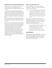
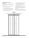
TEMPERATURE F vs RESISTANCE R OF TEMPERATURE SENSOR
1.) If temperature difference is greater than 3°F, then
the control will continue to energize pump relay.
2.) If temperature difference is less than 3°F, then the
control will de-energize the pump relay.
3.) The control will next wait for 10 minutes before
repeating Step #1 (above).
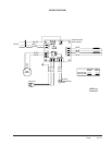
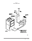
E. The Over Temperature Limit Switch is placed in series
with the line voltage. Therefore, continuity between L
of line voltage and L of pump output is forced broken
when the Over Temperature Limit Switch opens (see
Wiring Diagram).
F. The 3-amp fuse is put in series with the R connection to
the board. Whenever the fuse is blown, the control will
lose power and consequently, the relay will disengage.
Figure 5
THERMISTOR