


Manual 2100-506D
Page 5 of 14
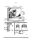
DRAIN: Connect a drain trap to the drain fitting under
the bottom of the dehumidifier section of the unit. The
drain connection is a ¾" female pipe fitting. The use of
a trap is required to ensure proper drainage.
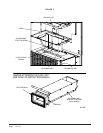
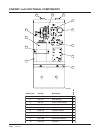
AIR CHANNEL ASSEMBLY: (See Figure 3.)
Remove cover plate in unit and cut out the insulation.
On CH3S1 models, the duct extension is to be removed
and a new piece of foam (supplied) added to the bottom
of the air channel assembly. Slide the air channel
assembly into the unit and position the assembly to the
left until the angle hits the side of the inner back.
Secure the angle with three self-drilling screws. Secure
the top with one screw.
SEQUENCE OF OPERATION
Dehumidification – Circuit DH makes at the humidistat
pulling in the compressor contactor, starting the
compressor and the dehumidifier blower motor. The
“G” (indoor motor) is automatically completed on call
for dehumidification (Relay #2).
The dehumidifier may operate alone or run
simultaneously with the first stage of the CH unit. When
the CH unit switches to second stage, the operation of the
dehumidifier will be locked out (Relay #1).
The Compressor Control Module is an anti-short cycle/
lockout timer with high and low pressure switch
monitoring.
On initial power up or any time power is interrupted to
the unit, the delay on make period begins, which will be
two minutes. When the delay on make is complete and
the high pressure and low pressure are closed, the
compressor contactor is energized. Upon shutdown, the
delay or break timer starts and prevents restart until the
delay on break and delay on make have expired.
During routine operation of the unit with no power
interruption, the compressor will operate on demand
with no delay.
HIGH PRESSURE SWITCH AND
LOCKOUT SEQUENCE
If the high pressure switch opens, the compressor
contactor will de-energize immediately. The lockout
timer will go into a soft lockout and stay in soft lockout
until the high pressure switch closes and the delay on
break time has expired. If the high pressure switch
opens again in the same operating cycle, the unit will go
into manual lockout. Recycling the wall humidistat
resets the manual lockout.
LOW PRESSURE SWITCH
BYPASS & LOCKOUT SEQUENCE
If the low pressure switch opens for more than 120
seconds, the compressor contactor will de-energize and
go into a soft lockout. Regardless the state of the low
pressure switch, the contactor will re-energize after the
delay on make time delay has expired. If the low
pressure switch remains open longer than 120 seconds,
the unit will go into manual lockout. Recycling the wall
humidistat resets the manual lockout.
NOTE: Both high and low pressure switch controls are
inherently automatic reset devices. The high pressure
and the low pressure switch cut out and cut in settings
are fixed. The lockout features, both soft and manual,
are a function of the compressor control module.
FREEZE STAT OPERATION:
The freeze stat
operation will open at 32° and de-energize the
compressor and fan. The compressor and fan will restart
after the coil defrosts and the freeze stat warms to 57°.
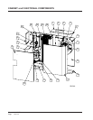
PRESSURE SERVICE PORTS
High and low pressure service ports are installed on the
unit, so the system operating pressures can be observed.
To gain access to these pressure ports, remove the long
narrow panel on the right-hand side of the outdoor
section of the CH unit. See Figure 4.
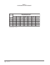
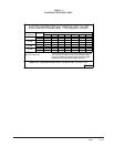
Reference the pressure table located on the front lower
panel and Table 2 within this manual.