


997-060180-4d
4
INSTALLER
INFORMATION /
ADVANCED FEATURES
SAFETY CONSIDERATIONS
Improper wiring or installation may damage controller. Wiring must
conform to local and national electrical codes
INTRODUCTION
The controller is a wall mounted, 24VAC low-voltage controller which
maintains room temperature by controlling the operation of a heating and air
conditioning system. Batteries are not required; temperature and mode
settings are preserved with the power off.
INSTALLATION CONSIDERATIONS
The controller requires no batteries. The controller is not a power stealing
device and MUST have both R and C connected.
INSTALLATION
IV. CONTROLLER LOCATION
Controller should be mounted:
- Approximately 5 ft. (1.5m) from floor.
- Close to or in a frequently used room, preferably on an inside
partitioning wall.
- On a section of wall without pipes or duct work.
Controller should NOT be mounted:
- Close to a window, on an outside wall, or next to a door leading
to the outside.
- Exposed to direct light and heat from a lamp, sun, fireplace, or
other temperature-radiating object which may cause a false reading.
- Close to or in direct airflow from supply registers and return-air grilles.
- In areas with poor air circulation, such as behind a door or in an alcove.
V. INSTALL CONTROLLER
1. Turn off all power to unit.
2. If an existing thermostat is being replaced:
A. Remove existing thermostat from wall.
B. Disconnect wires from existing thermostat, one at a time. Be
careful not to allow wires to fall back into the wall.
C. As each wire is disconnected, record wire color and terminal
marking.
D. Discard or recycle old thermostat.
NOTE: Mercury is a hazardous waste and MUST be disposed of
properly.
3. Separate the front and back pieces of plastic.
4. Route thermostat wires through hole in back piece of plastic. Level plastic
against wall (for aesthetic value only - thermostat need not be leveled for
proper operation) and mark wall through 2 mounting holes.
5. Drill two 3/16-in. mounting holes in wall where marked.
6. Secure back plastic to wall with 2 anchors and screws provided making
sure all wires extend through hole in plastic.
7. Use minimum of 22-gauge wiring, 18-gauge is recommended, for basic
controller wiring. Shielded twisted pair should be used for optional remote
indoor and outdoor sensors. Connect wires to proper terminal of the
connector block in the front plastic.
8. Push any excess wire back into wall. Excess wire inside the controller
plastic case can interfere with proper air flow across the temperature
sensor. Seal hole in wall to prevent air leaks. Leaks can affect operation.
9. Snap front and back pieces of plastic together.
10. Turn on power to the unit.
VI. INSTALLER SETTINGS
NOTE: These options are intended to be used by the installer. End users
are not advised to change or modify any of these settings. Doing so may
make your equipment stop working properly and/or may void the warranty
of the controller as well as the equipment hooked up to the controller. To
access the installer setting menu, the mode must be set to OFF. Then, press
both the up and down arrows keys at the same time for at least 5 seconds to
enter the installer screen.
MODEL CONFIGURATION
Options to select from:
HEAT COOL/HEAT PUMP,
SINGLE STAGE/MULTI STAGE,
ECONOMIZER/NO ECONOMIZER
CS2000A INSTALLED..YES OR NO
PROGRAMMABLE/NONPROGRAMMABLE
BOLD items are default
NOTE: - If CS2000A is installed, the controller will inhibit all outputs
except the Y0/D when there is no 24Vac applied to the L input on the
thermostat. When the CS2000A is not installed, the L input is the Lock out
signal from the heat pump.
ACCESSORIES
Each of these options has settings for Cumulative Run Time and Calendar
Time. Messages will flash at the top of the Main screen when these events
are met to alert the owner that it is time service these options.
Air Filter - Cumulative Run Time default is 1000 hours and Calendar Time
is 3 months. Values can range from 400-3600 hours for
Cumulative Run Time (in 100 hour increments), or Calendar
Time can be set to OFF, or 1-48 months (in 1 month
increments).
Humidifier - Cumulative Run Time default is 0 hours (OFF) and Calendar
Time is OFF. Values can range from 400-3600 hours for
Cumulative Run Time (in 100 hour increments), or Calendar
Time can be set to OFF, or 1-24 months (in 1 month
increments).
UV Lamp - Cumulative Run Time default is 0 hours (OFF) and Calendar
Time is OFF. Values can range from 400-12000 hours for
Cumulative Run Time (in 100 hour increments), or Calendar
Time can be set to OFF, or 1-48 months (in 1 month
increments).
Air Cleaner - Cumulative Run Time default is 0 hours (OFF) and Calendar
Time is OFF. Values can range from 400-3600 hours for
Cumulative Run Time (in 100 hour increments), or Calendar
Time can be set to OFF, or 1-24 months (in 1 month
increments).
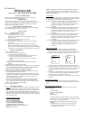
INPUT DEALER INFO
Contractors are able to input Brand Name, Unit Model Number,
Contractor Name, and Contractor Phone number into these screens.
This way, the owner could give this information to the contractor so that
he would know what system the owner has prior to the service visit.
1. Scroll to the info you want to enter and press the center button ■.
2. Enter the information by scroll through the characters using the up &
down arrows
▲▼. Once the character you want is set, press the right
arrow ► to move to the next space and begin entering another
character.
3. Once you’ve completed filling out the field, press the center button
■
to save the entry and return to the INPUT DEALER INFO screen.
Repeat this process for all fields you want saved.
4. Once all fields have been entered, scroll to SAVE and press the center
button ■.
FAN WITH HEAT OPTION
Options are ON or OFF. This selection determines whether G (fan)
output is to be ON or OFF when W (auxiliary heat) output is ON. Default
is ON.
DEHUMIDIFICATION CONTROL
If your system is equipped with dehumidification circuit, this output
controls that function.
OCCUPIED ONLY
FULL TIME DEHUMIDIFY
NONE
DIFFERENTIAL
To adjust the Set Point for Dehumidification, Select the RH from
the Main menu. The values can be selected and adjusted from that
screen. Range is 45-95%, default is 60%.
NOTE: Humidity can be displayed even if not being actively
controlled.
OCCUPIED ONLY - Turns on the D output when the room
humidity is above the set humidity level only during the
OCCUPIED (ACTIVE) time.
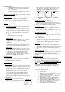
INPUT DEALER INFO
BRAND NAME
MODEL NUMBER
CONTRACTOR NAME
CONTRACTOR PHONE
SAVE
SELECT OPTION
∇∆
⊲
PREVIOUS
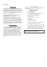
BRAND NAME
DEALER INFO
BRAND NAME
USE
∇∆
TO SCROLL
THRU CHARACTERS
A
_____________________________
CHANGE LETTER
∇∆
⊲
PREVIOUS
A