


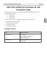


AXIS T90C10/T90C20 Installation Guide Page 9
ENGLISH
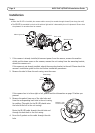
5. Plug the gaskets into the side and back holes. The gaskets should fit snugly in the holes with no
folds or bends.
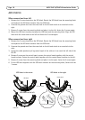
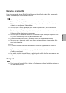
6. Place the IR-LED beneath the unit casing
aligning the screw hole on the back of the
IR-LED with the screw hole in the unit
casing; screw the IR-LED on to the unit
casing with the single screw.
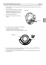
7. Attach the unit casing to the mounting
bracket.
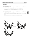
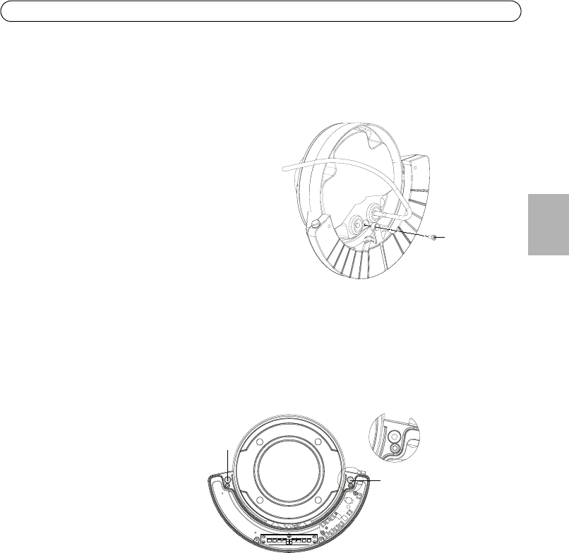
8. For vandal-resistant installation do the following:
a. Detach the cover on the IR-LED.
b. Screw the IR-LED to the wall with 2 screws.
c. Replace the cover after ensuring the gasket is in place.
9. Connect the network cable from the IR-LED to the PoE switch or midspan (AXIS T90C20); or
connect the DC cable to the PSU (AXIS T90C10).
10. To complete the camera installation please refer to the installation guide provided with the
network camera.
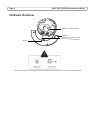
Screw IR-LED
Back view
Screw here
Screw here
Front view