


MODELS 341A-342A-344A
4
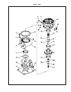
13. The seal flexible cup and stationary seat should be pressed
out of the bracket (35) and the cavity cleaned of all residue.
Make sure that the 1/32 inch radius in the seal seat cavity is
not damaged during disassembly since a sharp edge can eas-
ily cut the flexible cup during reassembly.
14. On Model 344A pumps, remove key (42) from the shaft and
remove slingers (47 and 47A).
15. Unscrew capscrews (48) and remove bearing cap (49).
Remove “O” ring (oil lubed only) (50) and retainer ring
(52).
16. Slide out shaft (55) and bearings (53 and 54). Since bearings
(53 and 54) are press fitted on the shaft, they will have to be
pulled or pressed off the shaft. Remove grease seals (51)
from frame (57), and bearing cap (49).
17. Remove nameplate (34) and screws (33) only if replacement
is needed.
REASSEMBL
Y
Reassembly will generally be in reverse order of disassembly. If
disassembly was not complete, use only those steps related to
your particular repair program.
1. Press grease seals (51) into frame (57). (344A)
2. Press bearings (53 and 54) onto shaft (55). Snap retainer
ring (52) into place. (344A)
3. Slide shaft (55) and bearings (53 and 54) into frame (57)
until retainer ring on bearing (54) comes in contact with
frame (57). Place “O” ring (oil lubed only) (50) in place.
(344A)
4. Fasten bearing cap (49) in position with capscrews (48).
Insert grease seals (51A) and position slingers (47 and 47A)
on the shaft. (344A)
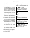
5. The mechanical seal (27) (see Figure 1) cannot be installed
as an assembly. It is necessary to have the seal seat properly
in place in bracket (35) before the balance of parts can be
added.
Thoroughly inspect the seal cavity in seal bracket, checking
for burrs or nicks which could damage flexible cup of
mechanical seal. Apply a film of liquid dishwashing deter-
gent (do not use oil or grease) to the flexible cup and seal
seat. Insert seat in cup and install in seal bracket, taking care
to seat it evenly and squarely.
NOTE
If it is not possible to insert seat with fingers, place the
cardboard protecting ring furnished with seal over
lapped face of seat and press into place with a piece of
tubing having end cut square. Tubing should be slightly
larger than the diameter of the shaft. Remove cardboard
after seat is firmly seated.
6. On Model 344A pumps, mount bracket (35) by screwing
capscrews (32) evenly into frame (57) to assure proper
alignment. Turn all capscrews in an even amount. Fasten the
bracket and frame to supports (41 and 64) by placing wash-
ers (40 and 63) over capscrews (39 and 62) and screwing
them into position.
On Model 341A and 342A pumps position bracket (35) on
the motor and secure with capscrews (32). Tighten screws
evenly to assure proper alignment.
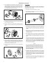
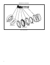
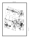
H. Shaft Assembly Removed.
G. Bearing Cap and Slinger Removed.
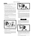
F. Bracket and Slinger Seal Flexible Cup and Stationary Seat Removed.
E. Support Feet Removed.