


MODELS 341A-342A-344A
3
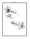
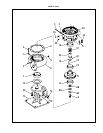
DISASSEMBLY
Disassemble only what is needed to make repairs or accomplish
inspection. (See Figure 2 for Model 341A, Figure 3 for Model
342A and Figure 3 for Model 344A.)
1. Disconnect and lockout power source to prevent drive unit
from being energized during disassembly.
2. Unscrew the two drain plugs (4) from the casing (6). On
Model 342A pumps, remove plugs (74 and 75) to drain
pump. Also unscrew the two plugs (4) from casing (6).
3. Remove all relief, cooling, flushing or drain lines from
pump, including compression connections (1 and 2) and
tubing (3). Break suction and discharge connections unless
it is intended to remove the power frame or motor assembly
and leave casing (6) in the line. On Model 342A pumps,
break discharge connections only, unless it is desired to
remove base (73). Remove capscrews (39) and lift pump
assembly from base (73). Remove gasket (72).
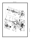
4. On Model 344A pumps, remove the flexible coupling from
between the pump and motor. Next unscrew the bolts that
hold support(s) (41 and 64) to the base and slide the pump
out to be worked on.
5. Remove capscrews (5) and pull casing (6) from bracket
(35). Remove gasket (8).
6. Unscrew impeller screw (9) and remove washer (9A), tak-
ing care not to damage gasket (9B) or capscrew seal (9C).
7. Slide impeller (11) and impeller key (12) from the shaft,
again taking care not to damage gasket (10) located behind
impeller. Remove gasket (10).
8. Wearing ring(s) (7 and 16) are pressed into their housings
with an interface fit and must be removed with a puller.
New ring(s) should be used for reassembly since it is likely
that during removal this fit will be lost. Do not remove
wearing rings if not being replaced.
9. Impeller wearing rings (optional - 14 and 15) are pressed
on and must be cut off if replacement is necessary. If they
are turned off in a lathe, take care not to cut into the
impeller.
10. Slide sleeve (25) with rotating parts of mechanical seal (27)
from the shaft. The sleeve should be carefully cleaned to
remove any residue that may be remaining in the seal area.
The rubber in seal (27) may have become partially adhered
to the sleeve. The sleeve must also be checked for abrasion
or corrosion that can occur when fluid residue penetrates
between the seal (27) and sleeve (25). The sleeve under the
seal may be polished lightly to a 32 RMS finish before
reassembly. Do not reuse a pitted sleeve. Pin (61) may be
removed if necessary.
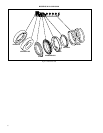
The mechanical seal (see Figure 1) is a precision product
and must be treated as such. During removal, great care
must be taken to avoid dropping any part of the seal.
Take particular care not to scratch the lapped faces on the
washer or the sealing seat. If any wear of the seal faces is
noted, it is recommended to replace with a new seal dur-
ing reassembly.
11. On Model 344A pumps, remove capscrews (39 and 62) and
washers (40 and 63) to take off support feet (41 and 64). On
Model 341A frame size 143 thru 184-JM only, unscrew cap-
screws (39) washers (40) and remove support (41) from
bracket (35).
12. Unscrew capscrews (32) to remove bracket (35) from frame
(57) or motor on Models 341A and 342A.
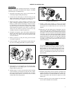
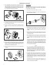
D. Mechanical Seal Removed.
CAUTION
C. Impeller and Key Removed.
B. Casing, Gasket, and Wearing Ring Removed.