


© 1999 Audiovox Corp., 150 Marcus Blvd., Hauppauge, N.Y. 11788 128-5338A
-5-
5 WIRE ALTERNATING DOOR LOCK CIRCUITS:
In this application, it is necessary to cut the existing door lock by-pass wires. These wires run from the master door
lock switch to the slave door lock switch, and then on to the door lock motors.
Cut the existing lock wire, and connect the yellow wire to the slave switch or motor side of the cut wire. Connect the green
wire to the master switch side of the cut wire.
Cut the existing unlock wire, and connect the white wire to the slave switch or motor side of the cut wire. Connect the
blue wire to the master switch side of the cut wire.
The orange and blue w/white stripe wires must be connected to a fused +12 VDC battery source.
Refer to the AUDIOVOX Door Lock Wiring Supplement for proper connection of these wires into the various locking
circuits available in current vehicles.
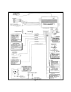
6 PIN DOOR LOCK OUTPUT CONNECTOR: 2-STEP OPERATION
When wiring for 2-step unlock operation, you must connect the outputs of the on-board unlock relay to the driver's side
door lock motor. Wire these outputs as follows;
Orange = N.O. Relay Contact to +12 VDC Battery
Dark Blue = N.C. Relay Contact to Motor leg switch side
White = Common Relay Contact to Motor leg motor side
Wire the transistorized negative "all doors unlock" output directly to the negative unlock wire from the door lock switch
in vehicles with 3 wire ground switched circuits.
In vehicles with 3 wire positive or 5 wire alternating switched circuits, you must add a 30 Amp automotive relay to provide
the "all doors unlock" feature.
RED w/BLACK & GREEN w/BLACK 2 PIN RED CONNECTOR: 2-STEP UNLOCK CONNECTOR
The Green w/Black tracer wire provides a 300 mA ground pulse output for the all doors unlock signal, and can be
connected to the negative door unlock wire in 3 wire negative switched vehicles.
The Red w/Black tracer wire provides a +12 VDC source for those applications that require a relay for the all doors unlock
feature.
COMPLETING THE INSTALLATION:
ANTENNA WIRE: Be sure to extend the thin black antenna wire to its full length, and cable tie into place where it cannot
be damaged. Avoid wrapping this wire around major, high current wire looms.
OPERATION: Take a few moments to check off the appropriate option boxes in the owner’s manual, and to fully explain
the operation of the system to your customer.
WIRE DRESSING: Always wrap the alarm wires in convoluted tubing, or with a spiral wrap of electrical tape. Secure these
looms along the routing using cable ties.
This will ensure that the alarm wires are not damaged by falling onto hot or sharp moving surfaces in the vehicle.