


-4-
ORANGE WIRE: 300 mA GROUND OUTPUT WHEN ARMED
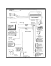
This wire is provided to control the optional (not included) starter cut relay. Connect the orange wire to terminal 86 of
the AS 9256 relay (or an equivalent 30 A automotive relay), and wire the remaining relay contacts as shown in the wiring
diagram.
IMPORTANT: Audiovox does not recommend using this relay to interrupt the ignition wire. Only
connect this relay to the low current starter solenoid feed wire, as indicated on the wiring diagram.
WHITE WIRE: 300 mA PULSED GROUND PARKING LIGHT OUTPUT
This wire is provided to control an optional ( not included ) parking lamp flasher relay. Connect the white wire to terminal
86 of the AS 9256 relay ( or an equivalent 30 A automotive relay ), and wire the remaining relay contacts as shown in
the wiring diagram.
DARK GREEN w/ BLACK TRACE WIRE: LATCHING OUTPUT / CHANNEL 3
The green w/ black tracer wire latches to ground via an independent RF channel from the keychain transmitter. This
is a transistorized, low current (300 mA.) output, and should only be used to drive an external relay coil.
This wire provides an immediate ground signal, and stays at ground for as long as the buttons on the keychain transmitter
remain pressed.
WARNING! Connecting the dark green w/ black tracer wire to the high current switched output of trunk release
circuits, some remote starter trigger inputs, and some window roll up trigger inputs, will damage the control module.
Connect the dark green w/ black tracer wire to terminal 86 of the AS 9256 relay (or an equivalent 30 A automotive relay),
and wire the remaining relay contacts to perform the selected function of channel 3.
2 DARK BLUE WIRES: PULSED OUTPUT / CHANNEL 2 (TRUNK RELEASE)
The dark blue wires are controlled via an independent RF channel from the keychain transmitter. These are the NO and
COMMON contacts of an on board, 10 A relay, so they can be connected to positive or negative switched circuits.
Connect one of the dark blue wires to the output of the trunk release push-button switch, and the other dark blue wire
to either chassis ground, or + 12 VDC battery, depending on the polarity of the trunk release circuit in the vehicle.
When using this channel for an accessory other than trunk release, connect one dark blue wire to the accessory, and
the other dark blue wire to either chassis ground, or, to a fused + 12 volt battery source, depending upon the requirements
of the accessory.
WARNING: Never attempt to pull more than 10 Amperes of current through this relay. The circuit will be damaged.
Always check the requirements of accessories prior to connecting them to the circuit.
LOCK RELAY UNLOCK RELAY
BLUE/WHITE = N.O. CONTACT ORANGE = N.O. CONTACT
GREEN = N.C. CONTACT BLUE = N.C. CONTACT
YELLOW = COMMON CONTACT WHITE = COMMON CONTACT
3 WIRE GROUND SWITCHED DOOR LOCK CIRCUITS:
In these vehicles, the dark green and dark blue door lock wires are not used.
The orange and blue w/white stripe wires must be connected to a chassis ground source.
The yellow wire is the ground pulse "lock" output, and should be connected to the negative lock wire in the vehicle.
The white wire is the ground pulse "unlock" output, and should be connected to the negative unlock wire in the vehicle.
3 WIRE POSITIVE SWITCHED DOOR LOCK CIRCUITS:
In these vehicles, the dark green and dark blue door lock wires are not used.
The orange and blue w/white stripe wires must be connected to a +12 volt battery source.
The yellow wire is the positive pulse "lock" output, and should be connected to the positive lock wire in the vehicle. The
white wire is the positive pulse "unlock" output, and should be connected to the positive unlock wire in the vehicle.