


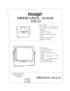

AOS-33 Operations Manual
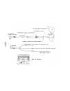
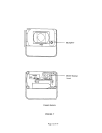
FUNCTIONS AND OPERATION, CONTINUED Rear of Monitor'
1 Power connection' 1 not used
2 Ground -black wire
3 Reverse circuit -blue wire
4 not used
5 not used
6 i-12VDC ignition -red wire
2, Camera A input connection to camera extension cable
3, Camera B input connection to additional camera extension cable
4 External speaker connection center pin is positive audio output. Used to disable the internal speaker and
remotely mount a speaker for driver convenience
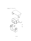
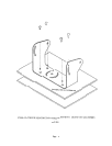
CAMERA COMPONENTS AND CONTROLS
Camera'
1. Microphone -waterproof microphone for audio pickup,
2. MirrorlNormal switch -waterproof switch to change camera image from a mirror view (rear of vehicle
mounted) to normal view (side or front mounted camera) See Figure 7.
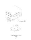
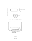
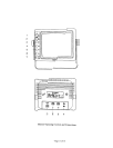
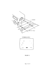
AFFIX'NG DISTANCE MARKERS TO THE MONITOR SCREEN
2.
Clean monitor screen surface of fingerprints. Set the camera into the "OOWNK position Place distance indicators
behind the vehicle at (3) feet, (6) feet and (9) feet along the width of the vehicle. These distances are measured
from the rear bumper. (Refer to figure 8.)
Attach the markers to the monitor screen over the images of the distance indicators. These markers represent a
distance of (3) feet, (6) feet, and (9) feet from the back of the vehicle. (See Fig 8) .
Affix the "STOP" marker on the monitor screen over the image of the rear bumper to locate the rear bumper.
The monitor screen is now "calibratedK for distances behind the vehicle of (3) feet, (6) feet and (9) feet
3
4.
Page 4 of 14 -