


AOS.33 Operations Manual
MAINTENANCE:
Remove dust and dirt with 'd damp ~oft cloth. Heav;er dirt should be removed with a damp soft cloth and mild deteT9~f)t.
Do not use strong cleaning agents containing gasoline, thinner. benzene or alcohol. These substances may damage the
exterior surface of the monitor.
**CAUTION**
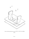
, Before drining, be sure no cable or wiring is on the other side. Be sure to dril1 a '6mm l'518l diame\er'110)e on)y
2 Feed as much cable as possible into vehicle and clamp secur~ly. This reduces the possibility of being hooked
during production.
3. Keep all cables away from HOT, ROTATING and ELECTRICALLY NOISY components.
4. To increase protection of cable, place all excess wire and extension cable in convoluted tubing
5. Do not tWist camera cable and do not cut camera pigtail or cable
WIRING CAMERA AND MONITOR
1
2
3.
4
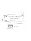
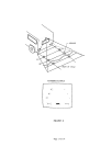
See wiring diagram for connections to ignition, ground and back-up circuit (See Fig. 6)
Winng camera:
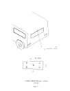
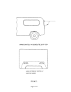
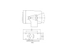
Drill a 19mm(V4;;j!diameter hole into vehicle body near the camera and bracket.
ConneCTcamera--connector to extension cable in vehicle.
Push extra cable if)to vehicle (Be tQ(eful no1. \0 \t."11)r.. cable) and fIt grl)lTIme\ in\o ho\e.
Apply sealant around grommet to increase resistance to water penetration.
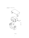
Wiring Monitor:
Insert extension cable into camera #1 position If (2) camerCIs are used, be sure to mark each extension
cable proper\'j '3\"\<i p\ug secol\d cable if\to camera #2 position.
But\dle exce~s c"dble together usit\g a c'3b\~ tie Q( 'li\1'1\ tape .lhis 'fi\" "i\'lQi<i pos$ible <iamage to cable.
during operation.
The red Wire marked ACC is connected to an ignition power source, the black Wire marked GNO is
co/)nected to chassis ground. and the blue wire marked BACK is connected to the vehicle's back. up circuit
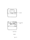
FUNCTIONS AND OPERATION
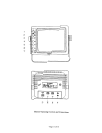
Monitor:
1. Power switch'
2 Camera position:
3. Input switch:
4. Contrast:
5 Brightness
6. Volume:
7. Day/Night switch:
STD. BY -Monitor operates when vehicle transmission is switched into ffREVERSE«
ON -Monitor and system operate when ignition switch is "ON"
UP- Panoramic view of the horizon, if camera is in "UP" position
DOWN- Directed view of the rear of the vehicle, if camera is in "DOWN" position
"A." -used mainly for rear mounted camera or as specified by the installer
"8" -used mainly for side or mirror mounted camera or as specified by the installer.
Variable control of contrast. Should be adjusted if the "DAY/NIGHT" switch does not
achieve the most desirable picture.
Variable control 01 brightness. Should be adjusted il the "DA'fJN\GHj" switch does r.Qt
achieve the most desirable picture.
Variable control of internal speaker and external speaker volume.
Pre-set brightness and contrast levels optimized for day and night operation.
-Page 3 of 14 -