Service Reference Manual UNIT COMPONENTS
5-11
SRM-HW/HWC 2/99
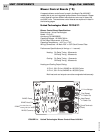
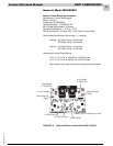
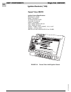
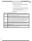
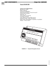
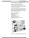
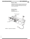
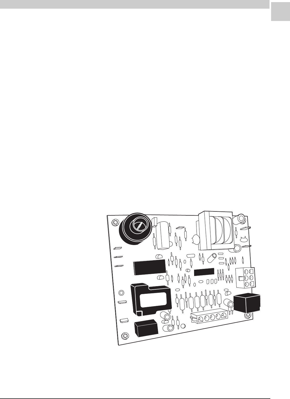
Integrated Blower/Ignition Control (*24)
United Technologies Model 1097-400-1
The integrated control combines the actions and purposes of the indi-
vidual ignition and blower control boards found on other units. It automati-
cally monitors and controls the operation of the gas burners, gas valve,
induced draft blower and circulating blower.
The control has a built-in diagnostic function, quick gas valve shutoff and
automatic ignition retry when it detects that a fault condition has been
corrected. If a fault is detected, the controls goes into fault mode and
flashes the single LED indicator at a preset rate for that particular fault
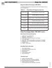
condition. (See Diagnostic Flash Code found in Table 4-1 on page 4-8 or
Diagnostic Indicator code printed on unit label.)
U
N
U
S
E
D
AC
B
H
E
A
T
AC
B
C
O
O
L
F
LA
M
E
2
4
V
AC
G
R
O
U
N
D
CMB
BL
W
R
L1
Y
C
W
G
R
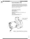
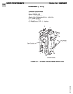
FIGURE 5-8 United Technologies Model 1097 Integrated Control
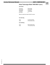
Integrated Control Specifications
Manufacturer: United Technologies
Model: 1097-400-1
Armstrong P/N 44990-001
Operating Temperature: – 40°F to +175°F
Timing Tolerance: +/– 10%
Input Voltage: 18-30VAC, 50/60 Hz
Combustion Blower: 1/8 HP @ 120/240VAC
Circulating Blower: 1/2 HP @ 120VAC, 1 HP @ 240VAC
Gas Valve: 24VAC, 60 Hz, 1.0 A


