


Service Reference Manual INSTALLATION
6-7
SRM-HW/HWC 8/99
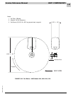
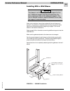
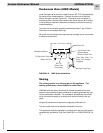
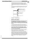
Condensate Drain (HWC Models)
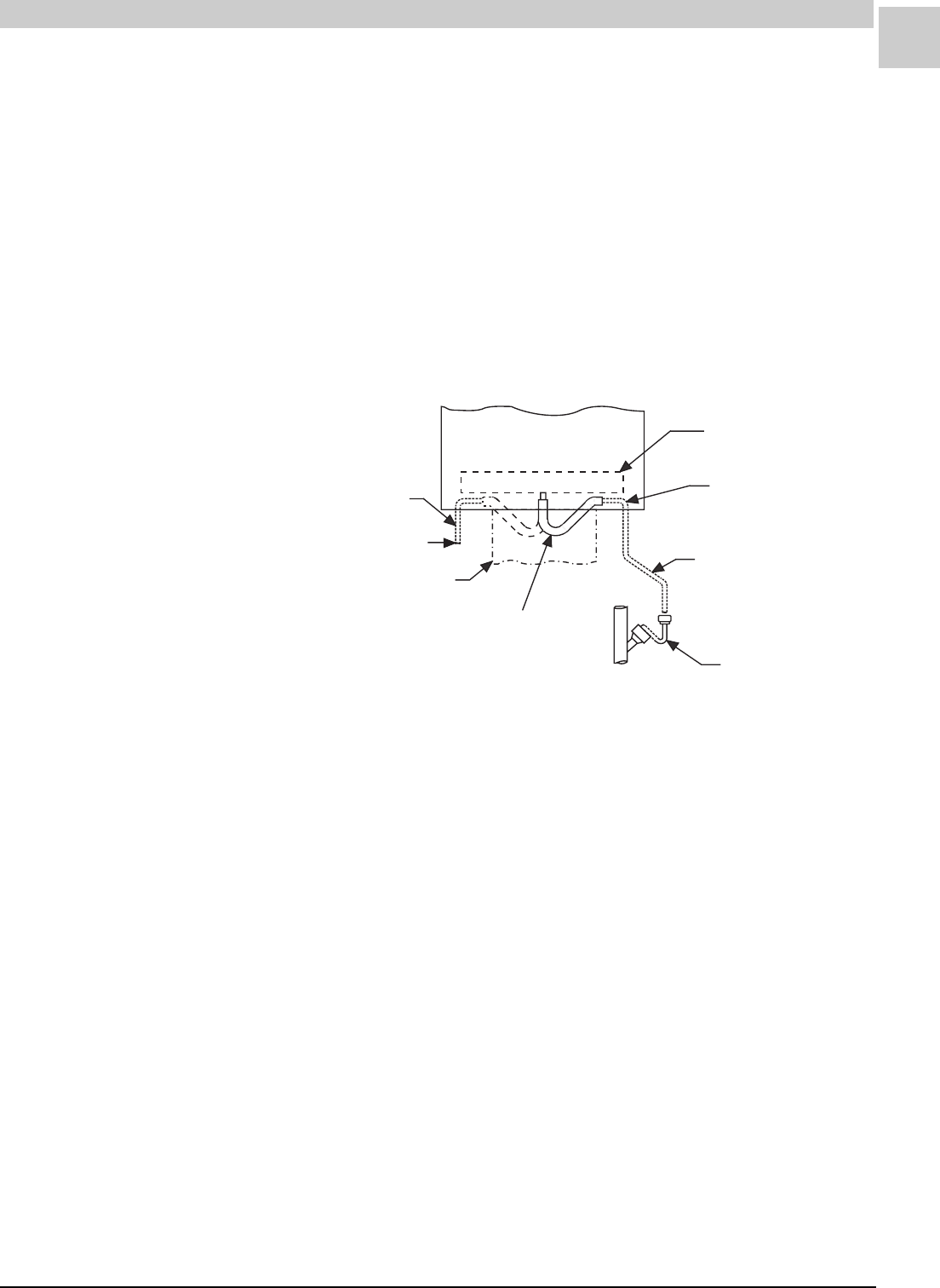
Install the plastic drain tube (furnished) over the 5/8" O.D. fitting welded to
the center of the condensate pan. Connect the other end of the drain
tube to the open trap (see Figure 6-2). The plastic drain connection is
provided so that it may be disconnected from the permanent drain tubing
in the building in the event it becomes necessary to remove the cooling
chassis assembly.
The drain line should pitch gradually downward at least 1" per 10 feet of
horizontal run to the open drain trap.
Be certain that the plastic drain tube has free drainage and is not crimped
or flattened at any bend.
Drain Pan
Top of Drain Tube
Must be Below
Bottom of Drain Pan
Drain Tube - Pitch 1" for
every 10 ft. (Installer
Supplied)
Open Drain Trap
5/8" I.D.
Plastic Tube
(Furnished)
Return Air Duct
To Open Drain Trap
Alternative Method
FIGURE 6-2 HWC Drain Installation
Venting
The venting system is an integral part of the appliance. The
venting system must not be modified or added on to.
HW/HWC units are direct vent forced air central furnaces which draw
fresh air from outside through a combustion air opening beneath the vent
into the combustion chamber. The combustion products are then drawn
out of the heat exchanger by an exhaust fan and are forced to the out-
doors.
No special provisions are required for supplying combustion air.
The vent outlet must not be altered or extended in any way.
This appliance should be installed in a location such that the vent system
complies with the National Fuel Gas Code Z223.1 or CAN/CGA-B149.1 &
.2.