


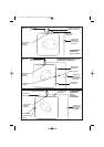
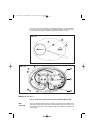

Heater can sit on floor.
Connect the cold water inlet pipe to the inlet nipple (marked with a blue ring) and the hot
water outlet pipe to the outlet nipple (marked with a red ring).
To reduce the risk of excessive pressures and temperatures in this water heater, install
the supplied temperature and pressure protective equipment required by local codes
but not less than a combination temperature and pressure relief valve certified by a
nationally recognized testing laboratory that maintains periodic inspection of
production of listed equipment or materials, as meeting the requirements for Relief
Valves and Automatic Gas Shut-off Devices for Hot Water Supply Systems, ANSI
Z21.22.The supplied temperature and pressure relief valve is marked with a maximum
set pressure (150 psi) that does not exceed the marked maximum working pressure
of the water heater. Install the valve in the opening provided and marked for this
purpose in the water heater, and orient it or provide tubing so that any discharge from
the valve will exit within 6 inches above, or at any distance below, the structural floor,
and cannot contact any live electrical part.The discharge opening must not be blocked
or reduced in size under any circumstances.
National Plumbing codes require a drain pan for any water heater installation. Failure
to install one is the sole responsibility of owner and/or installer. Reference UPC 2000
(Uniform Plumbing Code) Section 510- Protection from Damage or IPC 2000
(International Plumbing Code) Section 504- Safety Devices.
Periodic discharge of the temperature and pressure relief valve or failure of the
element gasket may be due to thermal expansion in a closed water supply system.
The water utility supply meter may contain a check valve, backflow preventer or water
pressure reducing valve which will create a closed water system. During the heating
cycle of the water heater, the water expands causing pressure inside the water heater
to increase.The temperature and pressure relief valve may discharge hot water under
these conditions which results in a loss of energy and a build-up of lime on the relief
valve seat.
To prevent this from happening, there are two recommendations:
1. Install a diaphragm-type expansion tank that is suitable for potable water on the
cold water supply line. The expansion tank must have a minimum capacity of 1.5
U.S. gallons for every 50 gallons of stored water.
2. Install a 125 PSI pressure relief valve in the cold water supply line. Make sure the
discharge of this valve is directed to an open drain and protected from freezing.
Contact the local water supplier or plumbing inspector for information on how to
control this situation. Do not plug the temperature and pressure relief valve.
Instructions for use
Before connecting the power, fill the tank and system with water and check for leaks. To
be certain that all air is out of the water system, open the hot water faucets on your fixtures
until constant water flows from them, otherwise damage to the element may occur.
To start the heating cycle:
A) first make sure tank is full. Otherwise the heating element may be damaged.
B) the red light will come on and remain on until that temperature has been reached,
at which point the light will go off, but will automatically come back on when the
water temperature drops below the setting chosen.
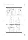
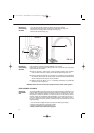
After installation check the water temperature. If adjustment is necessary, remove front
cover to adjust thermostat (D Fig. 4 -clockwise to increase the temperature and
counter clockwise to decrease it).
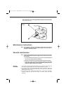
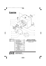
To reach the thermostat:
1. Pry off the round cover plate (V Fig. 3/1) from its right hand edge (W Fig. 3/1) with
a small flat-head screwdriver.
2. Remove the Phillips screw revealed beneath the round cover plate.
CAUTION
Closed
system
thermal
expansion
(for all
models)
Starting and
testing
Temperature
Setting
6
Pipe
connections
Floor
Mounting
29.1.60.542.1.04 libretto 19-01-2004 9:35 Pagina 6