


General remarks
The manufacturer cannot be responsible for the damages caused by improper
installation or by failure to follow instructions in this pamphlet. Comply with the
installation instructions before completing electric connection.
The thermostat has been pre-set at the factory between 41°C (105° F) and 45° C (113° F).
Hydrogen gas can be produced in a hot water system served by this heater that has not
been used for a long period of time (generally 2 weeks or more). Hydrogen gas is
extremely flammable. To reduce the risk of injury under these conditions, it is
recommended that the hot water faucet be opened for several minutes before using any
electrical appliance connected to the hot water system. If hydrogen gas is present, there
will probably be an unusual sound such as air escaping through the pipe as the water
begins to flow. There should be no smoking or open flame near the faucet at this time.
Any water heater should be installed in such a manner that if it should leak, the resulting
flow of water will not cause damage to the area in which it is installed.National Plumbing
codes require a drain pan for any water heater installation. Failure to install one is the
sole responsibility of owner and/or installer. Reference UPC 2000 (Uniform Plumbing
Code) Section 510- Protection from Damage or IPC 2000 (International Plumbing Code)
Section 504- Safety Devices.
CAUTION
CAUTION
CAUTION
CAUTION
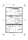
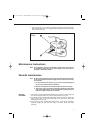
Installation instructions
Fasten the supplied mounting bracket to the wall. Use screws that are suitable for the
wall material and the weight of the heater. Hang the water heater on the bracket. Tug
down wards on the heater to ensure that both “fingers” of the bracket are seated in the
mounting slots. Confirm water piping orientation before wall mounting.Wall bracket will
not support the GL6+ when the plumbing connections are installed horizontally.
Heater can sit on floor. Confirm water piping orientation before locating on floor location.
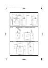
As per the National Electric Code the GL6+ needs to be wired with 12 GA. wire to a minimum
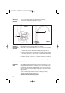
20 amp/ maximum 20 amp branch circuit. To wire the GL6+ model:
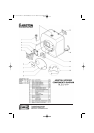
1. Pry off the round cover plate (V Fig. 3/1) from its right hand edge (W Fig. 3/1) with a
small flat-head screwdriver.
2. Remove the Phillips screw revealed beneath the round cover plate.
3. The cover (C Fig. 3/1) can now be removed by pulling out its left-hand edge. When
reassembling, work in the opposite way being careful to insert the tongue of the cover
into the slot.
4. Insert 12 AWG through conduit at rear of heater. Secure internal wire connector
(A Fig. 3/2) and connect wiring to right side of thermostat control and ground. Positive
(+) to lower terminal marked “L” (E Fig. 3/2) and Neutral to upper terminal marked “N”
(H Fig. 3/2). Unit must be grounded at groundscrew (T Fig. 3/2) on element base.
5. When the GL6+ is not within sight of the electrical circuit breakers, a circuit breaker
lockout or additional local means of disconnection for all non grounded conductors must
be provided that is within sight of the appliance. [REF NEC 422.31]
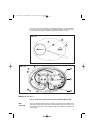
Connect the cold water inlet pipe to the inlet nipple (marked with a blue ring) and the hot
water outlet pipe to the outlet nipple (marked with a red ring).
The model GL 6+ can be piped horizontally from the side or vertically from the top. If you
wish to install the unit horizontally, with the piping connections on the right side, you will have
to be certain the tap between the two water tappings is plugged, the supplied Temperature
and Pressure Relief Valve will need to be installed on top. See location of T&P relief valve in
Fig. 2/2.
Wall
mounting
(only for vertical
installation)
MODEL GL 6+
Wiring
and
Grounding
instructions
Pipe
connections
Floor
Mounting
The GL 6+ water heater can be installed under the sink.
4
29.1.60.542.1.04 libretto 19-01-2004 9:35 Pagina 4