


2 3
INSTALLATION
THERMOSTAT INSTALLATION LOCATION RECOMMENDATIONS
EQUIPMENT CONTROL MODULE INSTALLATION LOCATION RECOMMENDATIONS
Thermostat should be mounted:
Equipment control module should be mounted:
140°F (60°C) or drop below 32°F (0°C).
Do not mount thermostat:
appliances that give off heat.
outside doors.
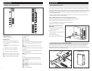
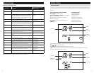
REMOTE TEMPERATURE SENSOR (OPTIONAL)
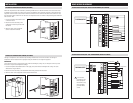
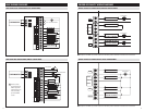
THERMOSTAT WIRING
A remote temperature sensor can be used if the thermostat is to be mounted in a concealed location. A 8051 flush
mount or 8053 surface mount remote temperature sensor can be attached to the T1 and T2 terminals and mounted
override the thermostat’s internal temperature sensor.
123T1T2
Remote temperature sensor should be
mounted:
space.
Do not mount remote sensor:
spaces.
other appliances that give off heat.
or near outside doors.
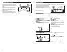
THERMOSTAT MOUNTING
EQUIPMENT CONTROL MODULE MOUNTING
1. Remove the rear mounting plate from the thermostat.
2. Pull wires through the opening on the back of the thermostat.
3. Position and level the mounting plate of the thermostat on
wall and mark the hole locations with a pencil.
6. Seal wire entry holes to prevent drafts affecting temperature
readings.
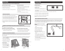
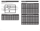
The Equipment Control Module has the following features to simplify mounting and wiring and provide for a clean
and neat installation.
be utilized. Mount the Equipment Control Module using 2 to 4 #8 screws appropriate for the mounting surface
substrate. (See Figure 2.)
to secure wires in 10 places.
Installation Steps
1. Select mounting location.
2. Pull from bottom to remove
front cover. (See Figure 1.)
3. Mount base using 2 to 4 #8
screws (field supplied).
123T1T2
INSTALLATION
Do not mount equipment control module:
ductwork. These locations can cause moisture to
condense on the equipment control module.
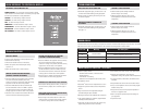
Wire specifications:
18-24 gauge thermostat wire
Installation notes:
and re-tighten.
1 – Connection to terminal 1 at equipment control module
2 – Connection to terminal 2 at equipment control module
3 – Connection to terminal 3 at equipment control module
T1 & T2 – Remote temperature sensor (optional)
Figure 1 Figure 2
Note:
loss of programs due to electrical discharge.