


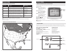
4 5
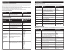
WIRING TERMINAL
Wire specifications:
18-24 gauge thermostat wire
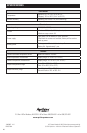
Installation notes:
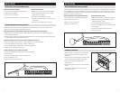
• Ensure power at the HVAC equipment is off.
• Loosen screw terminals, insert stripped wire and
re-tighten.
• Push the excess wire back into the opening and plug
the wall opening to prevent drafts.
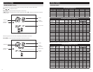
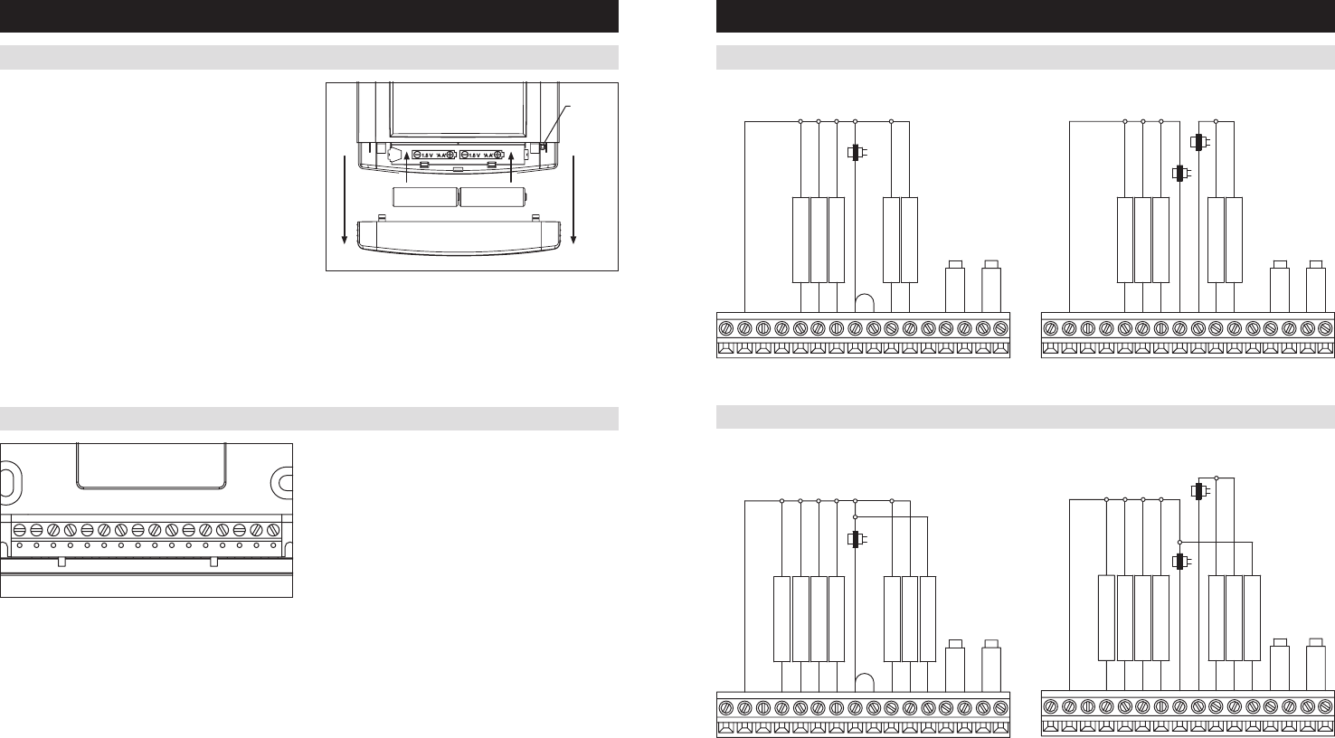
INSTALLATION
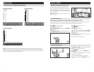
I1 & I2 – Indoor Air Quality control output
C – Common (optional when powered by batteries)
O/B – Reversing valve
Y – 1st stage cooling / compressor
Y2 – 2nd stage cooling / compressor
G – Fan
RC – 24VAC supply cooling
1
R – 24VAC supply heating
1
W2 – 2nd stage heat / auxiliary
W – 1st stage heat / auxiliary
L – System fault indicator (optional) (heat pump only)
S1 & S2 – outdoor temperature sensor (included)
T1 & T2 – remote temperature sensor (optional)
1
Jumper between RC & R is used in single transformer systems
(see wiring diagrams).
INSTALLATION
C I2
I1 Y
O/BRC
RG
Y2 W2
LT
2
T1
S1
S2
W
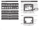
SINGLE TRANSFORMER (USE JUMPER WIRE) TWO TRANSFORMERS (REMOVE JUMPER WIRE)
JUMPER
OUTDOOR TEMP
SENSOR
1st HEATING
1st COOLING
FAN
2nd HEATING
2nd COOLING
NOT USED
TRANSFORMER
REMOTE TEMP
SENSOR
NOT USED
GY2YO/BI1 WRC RW2S2LCI2 S1 T1 T2
NOT USED
2nd COOLING
2nd HEATING
FAN
1st COOLING
1st HEATING
OUTDOOR TEMP
SENSOR
COOLING
HEATING
REMOTE TEMP
SENSOR
NOT USED
TRANSFORMER
TRANSFORMER
GY2YO/BI1 WRC RW2S2LCI2 S1 T1 T2
SINGLE TRANSFORMER (USE JUMPER WIRE) TWO TRANSFORMERS (REMOVE JUMPER WIRE)
2nd COMPRESSOR
2nd AUX HEATING
FAN
1st COMPRESSOR
1st AUX HEATING
OUTDOOR TEMP
SENSOR
JUMPER
FAULT DETECT
REVERSING VALVE
HEAT PUMP
TRANSFORMER
REMOTE TEMP
SENSOR
GY2YO/BI1 WRC RW2S2LCI2 S1 T1 T2
FAULT DETECT
OUTDOOR TEMP
SENSOR
1st AUX HEATING
1st COMPRESSOR
FAN
2nd AUX HEATING
2nd COMPRESSOR
TRANSFORMER
HEAT PUMP
HEATING
TRANSFORMER
REMOTE TEMP
SENSOR
REVERSING VALVE
GY2YO/BI1 WRC RW2S2LCI2 S1 T1 T2
CONVENTIONAL HEAT/COOL WIRING DIAGRAMS
HEAT PUMP WIRING DIAGRAMS
POWER & RESET OPTIONS
The thermostat is dual power. It can either be AC or
battery powered, or both (to provide backup power for
the clock). Batteries are optional if your thermostat was
wired to run on AC power when installed.
For heat pump systems the C terminal must be connected
to the common of the 24VAC transformer in order for the
system fault and emergency heat indicators to operate.
The thermostat has a memory backup that saves the
thermostat settings in case of a power interruption. The
system settings will be retained but the clock will reset
after 90 seconds with no battery or AC power.
The reset button located under the battery cover can
be used to reset the thermostat to factory defaults. The
system settings will also be reset to default.
Note: The reset button is disabled when the thermostat
is removed from the wall for programming.
RESET
BUTTON