


KNOB A
COVER B
BASE PLATE D
DEHUMIDISTAT C
ANCHOR F (x2)
SCREW E (x2)
BASE PLATE D
CUT WIRES
4”
-
6” LENGTH
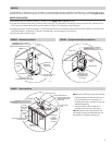
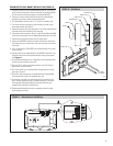
DEHUMIDISTAT WALL MOUNT INSTALLATION (FIGURE 10)
1. Gently pull knob (A) from the dehumidistat cover (B). The cover is
held in place by snap clips. Remove the cover by pulling carefully.
Do not touch the sensing element on the dehumidistat (C).
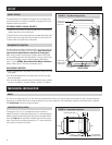
2. Remove 4 screws in base plate (D) and save for attaching the
provided cover plate in place of the dehumidistat.
3. Pull dehumidistat off unit until 4”- 6” of wire is outside of unit.
4. Cut wires and use metal tape to secure leads to inside of unit,
preventing contact with blower.
5. Remove the gasket from the base plate. This will be used with the
insulated cover plate installed in the next step.
6. Using the screws removed in Step 2, install the provided insulated
cover plate with gasket over the dehumidistat opening on the unit.
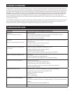
7. Remove the wiring access panel on unit outlet panel.
8. Unplug the REMOTE terminals from the circuit board, remove the
two wires and cut off bare leads. Once cut, the wires may remain
in the unit.
9. Run a 2-wire cable (18-22AWG) from the dehumidifier to the wall
mount location.
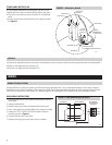
10. Connect cable at the dehumidifier to the REMOTE terminals. Plug
terminals into the circuit board and replace wiring access panel.
See Figure 11.
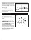
11. Use the dehumidistat base as a template to mark mounting holes
and wire access location on the wall.
12. Drill two 3/16” holes at mounting locations and a 3/8” hole at
desired wire access location.
13. Pull 2-wire cable from the dehumidifier through the wire access
opening in the wall.
14. Strip wire ends coming from the dehumidistat and dehumidifier
and connect with small, field supplied wire nuts.
15. Push excess wire and wire nuts through the access hole in the
wall. Use the supplied screws (E) and wall anchors (F) to attach
the base plate (with dehumidistat) to the wall using the top
centered hole and bottom centered slot.
16. Reassemble dehumidistat cover by snapping in place on base
plate and press on knob.
FIGURE 10 – Wall Mount
90-1466
FIGURE 11 – Dehumidistat to Unit Wiring
90-1465
5