


SET-UP
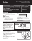
The dehumidifier can be installed as shipped, with the supply collar
on the outlet panel, or if space is restricted, the supply collar can be
relocated to the top of the unit.
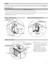
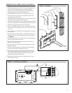
TOP MOUNT SUPPLY COLLAR (FIGURE 3)
1. Remove the four screws securing the supply collar (with backflow
damper) and screen to the outlet panel.
2. Remove the four screws securing the top mounted outlet cover plate.
3. Attach screen and supply collar with damper to the top of the unit.
4. Attach outlet cover plate to the outlet panel.
SUPPLY COLLAR
FIGURE 3 – Top Mount Supply Collar
The dehumidistat mounted to the dehumidifier can remain on the unit
or be removed and mounted in the living space. Attic installations
require that the dehumidistat be moved to the living space.
Note: Any dry contact, normally open humidity control can be used
as the controlling device for the dehumidifier. If using a control other
than the one provided, remove the dehumidistat as described in
steps 1-6 in the WIRING, Dehumidistat Wall Mount Installation
section. Follow steps 7-10 to wire an alternate control.
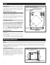
WALL MOUNT LOCATION
• Mount approximately 5 feet above the floor on an inside wall of the
living space.
• Do not locate dehumidistat in the direct path of drafts from open
doors and windows.
• Do not install where operation might be affected by lamps, outside
sources of humidity (i.e. shower), fireplace, registers, or radiators.
DEHUMIDISTAT LOCATION
90-1425
Supply collar
mounted to
top of unit
Outlet cover
plate moved to
outlet panel
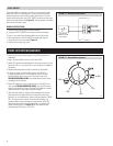
2-1/8" CLEARANCE
FOR LEVELING FEETVIBRATION ISOLATORS
FILTER ACCESS DOOR
OUTLET
INLET
5-1/8"
MECHANICAL INSTALLATION
Run vinyl or pvc tubing from the 3/4” drain outlet on the dehumidifier inlet to a floor drain. Make sure the drain line has a constant downward
slope and is not kinked. Refer to local codes to determine if a p-trap is required. In attic installations a drain pan with float switch is required.
See Float Switch section for wiring instructions.
DRAIN
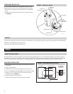
FIGURE 4 – Suspended Installation
If hanging the unit, use 1/4” threaded rod and two unistruts to
support the base just inside the leveling feet. It is recommended that
vibration isolators be placed between the unistruts and dehumidifier
base. See Figure 4. Do not position threaded rods over filter access
doors. There must be a minimum clearance of 12” on one side of the
unit to allow for removal of the filter.
SUSPENDED INSTALLATION
90-1427
OUTLET VIEW
2