


Service
Page 19
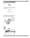
1. Disconnect pilot tubing and wires from gas valve.
2. Remove pilot assembly from burner tray.
3. Remove pilot from bracket.
4. Remove pilot orifice and air opening (Honeywell MV unit
only), and clean with wire or small brush.
CAUTION
DO NOT ENLARGE HOLE IN PILOT ORIFICE.
5. Reverse above procedure to reinstall.
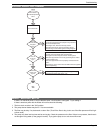
HEAT EXCHANGER REMOVAL
1. Shut water, gas and electricity off, close valves and
relieve pressure, then remove relief valve. Remove side
inspection panels.
2. Remove top jacket holding screws. Remove the jacket
top.
3. Remove the four (4) screws holding down the flue collec-
tor. Remove the flue collector.
4. Remove upper in/out access panel.
5. Disconnect all electrical wiring from in/out header.
6. Remove temperature sensor from in/out header.
7. Disconnect flange nuts on In/Out header.
8. Set aside heat exchanger side baffles.
9. Lift heat exchanger straight up using caution not to dam-
age refractory.
10. Reverse above procedure to reinstall.
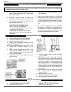
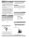
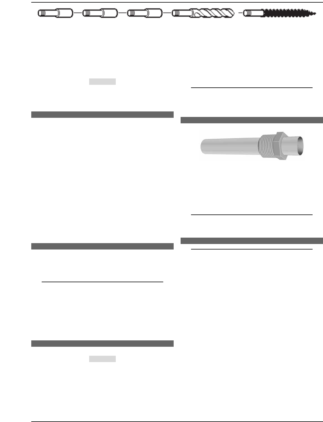
TUBE CLEANING PROCEDURE
Establish a regular inspection schedule, the frequency
depending on the local water conditions and the severity of
service. Do not let the tubes clog up solidly. Clean out
deposits over 1/16" in thickness.
NOTE: Please remove heat exchanger from heater
prior to reaming or removing debris.
After reaming, mount the wire brush in place of the auger
and clean out debris remaining in the tubes.
Another method is to remove the heat exchanger, ream
tubes and immerse heat exchanger in non-inhibited de-scale
solvent for severe scale build-up.
DESOOTING PROCEDURE
CAUTION
SOOT MAY BE COMBUSTIBLE. WET SOOTED SURFACES
COMPLETELY PRIOR TO CLEANING. DO NOT USE STEEL
WIRE BRUSH.
Soot will clog areas between fins and cause eventu-
al tube failure. Any sign of soot at the base of the burners or
around the outer jacket indicates a need for cleaning.
1. Remove top and flue collector from cabinet.
2. Remove "V" baffles from heat exchanger, including side
baffles.
3. Remove burner tray.
4. Remove heat exchanger from the heater and wash with a
garden hose, making sure soot is removed from spaces
between fins.
5. Reverse above procedure to reinstall.
NOTE: In extreme cases it may be necessary to do
high-pressure cleaning at a local car wash. DO NOT
WIRE BRUSH.
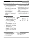
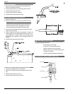
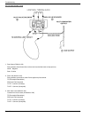
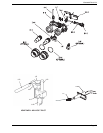
IMMERSION WELL REPLACEMENT - MILLIVOLT
Figure 33. Immersion Well Assembly.
1. Shut off water to heater and drain heat exchanger.
2. Remove access panel on water connection side.
3. Remove old immersion well with bushing and sleeve.
4. Install replacement well in header.
NOTE: Installation in polymer header should be
hand tight plus 1/2 turn.
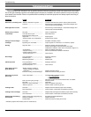
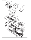
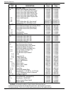
REPLACEMENT PARTS
NOTE: When ordering parts, it is important that the
heater model number, serial number, and type of
gas are specified.
Any part returned for replacement under standard compa-
ny warranties must be properly tagged with a return parts
tag, completely filled in with the heater serial number, model
number, etc., and shipped to the Company freight prepaid.
If determined defective by the Company and within war-
ranty, a like part or equal substitution will be returned, freight
collect. Credit will not be issued.
MANUFACTURER:
2151 EASTMAN AVENUE
OXNARD, CA 93030
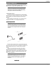
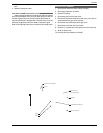
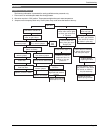
Extension Pieces (2)
Auger with Carbide Tip
Wire Brush
Figure 32. Tube Cleaning Tool.