


Installation
Page 11
ELECTRICAL CONNECTIONS
Be sure that electrical service to the heater has proper
overload fuse or circuit breaker protection, wire size and con-
nections which comply with all applicable codes.
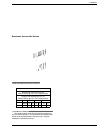
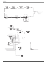
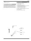
NOTE: If it is necessary to replace any of the origi-
nal wiring, use 105°C wire or its equivalent, and/or
150°C wire or its equivalent, like the original wiring.
See Figures 18 and 19 for wire ratings.
MILLIVOLT HEATERS
The Millivolt models are equipped with a self-generating
electrical system in which the electrical current is provided by
a pilot generator. No external electrical connections are
required.
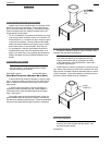
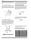
When installing a remote switch, do not exceed 10 ft of
wiring from the heater. Use 18-gauge stranded wire.
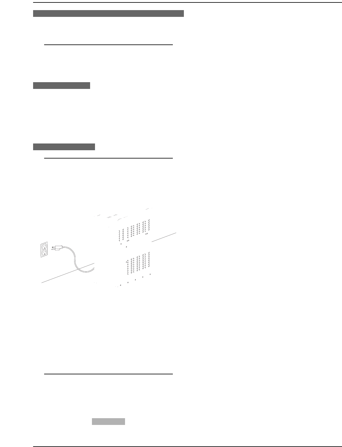
ELECTRONIC HEATERS
NOTE: Electronic heaters come standard with a
120 VAC 3-prong power cord. For 240 VAC applica-
tions, see instructions below. Power source must be
a wired ground, with ground fault circuit interruption
circuitry.
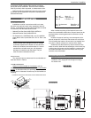
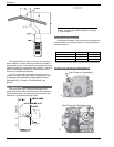
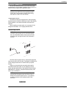
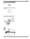
Figure 16. Electronic Heater Power.
The Direct Spark Ignition Device automatically lights the
main burners upon a call for heat. The heater is supplied with
a dual voltage transformer for 120/240 VAC input power
hookup.
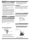
Heater must be electrically grounded and bonded in
accordance with local codes, or, in the absence of local
codes, with the latest edition of the National Electrical Code,
ANSI/NFPA 70. (Canada - Canadian Electrical Code, CSA
C22.1, Part 1 and Part 2.)
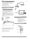
NOTE: Input power to the heater (120 VAC) can be
supplied from the load (pump) side of time clock or
directly from the GFCI power source. It is preferred
to make connection to the load/pump side of the
time clock.
WARNING
RISK OF ELECTRICAL SHOCK. MORE THAN ONE DIS-
CONNECT SWITCH MAY BE REQUIRED TO DE-ENERGIZE
THE EQUIPMENT BEFORE SERVICING.