


Installation
Page 10
High-temperature CPVC header flanges and header
flange nuts are available as an option. If there is any possi-
bility of back-siphoning when the pump stops, it is recom-
mended that a check valve (or valves) also be installed in the
system.
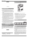
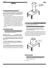
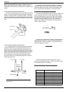
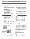
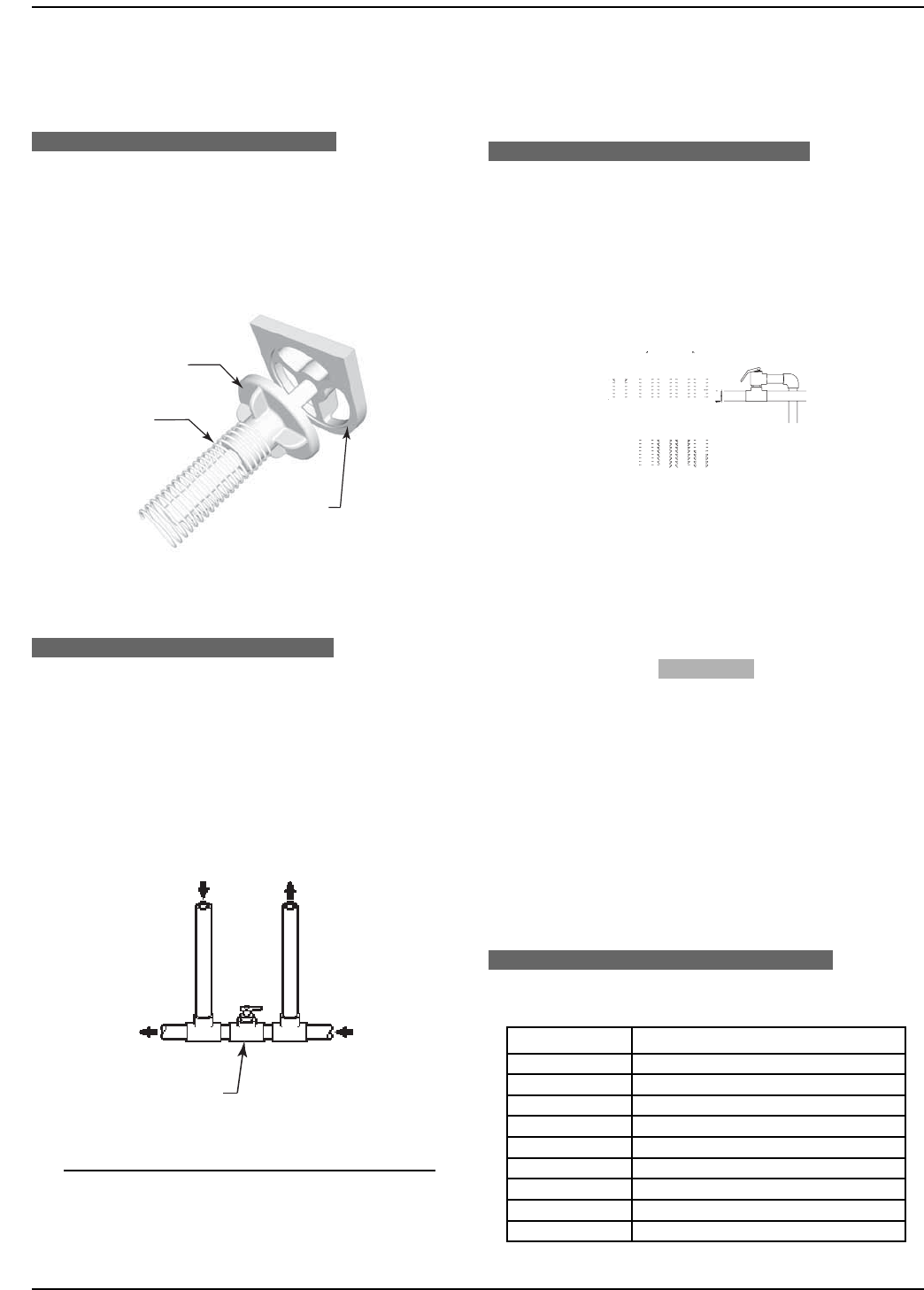
INTERNAL AUTOMATIC BYPASS VALVE
A built-in automatic bypass valve is provided in the In/Out
header. The internal bypass valve automatically responds to
changes in water pressure in the piping system. The proper
amount of water flow is maintained through the heater under
varying pressures dictated by the conditions of the pump and
filter.
Figure 13. Internal Automatic Bypass Valve
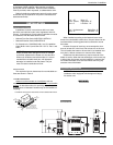
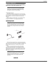
EXTERNAL AUXILIARY BYPASS VALVE
An auxiliary bypass valve must be used when flow rates
exceed 100 GPM. Usually a high-performance pump size
larger than one horsepower will exceed this flow rate. This
valve is required to complement the function of the automatic
bypass valve, particularly when starting the heater in winter
or early spring when the spa or pool temperature is below
50°F. It also serves to eliminate needless pressure drop
through the heater and accompanying reduction in the flow
rate to the spa jets, etc.
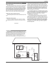
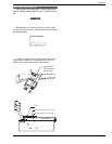
Figure 14. Auxiliary Bypass Valve.
NOTE: Do not use a gate valve as an auxiliary
bypass valve.
From Heater
To Heater
To Pool/Spa
Bypass Valve
From
Pool/Spa
Full Port
Ball Valve
or Globe
Valve
Bypass Disc
Spring
Bypass Body
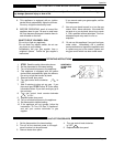
AUXILIARY BYPASS VALVE ADJUSTMENT
To set bypass: With clean filter, adjustment is made by
feeling the inlet and outlet pipes at the heater. Outlet pipes
should be slightly warmer than inlet and comfortable to the
touch. If pipe is hot, close bypass; if cold, open bypass.
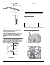
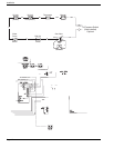
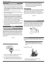
PRESSURE RELIEF VALVE INSTALLATION
To conform to local building codes, it may be necessary to
install a pressure relief valve. A 3/4" pressure relief valve,
having a capacity equal to the BTUH output of the heater to
be installed, is recommended for this heater. The maximum
pressure relief valve setting is 125 psi. This relief valve
needs to be installed on the outlet pipe from the header as
noted in Figure 15 below.
Figure 15. Pressure Relief Valve Installed.
If required, this needs to be installed in a field-supplied fit-
ting external to the heater. The valve shall be installed in a
vertical position. Do not overtighten. Install pressure relief
valve hand tight plus 1/2 turn.
WARNING
TO AVOID WATER DAMAGE OR SCALDING DUE TO
RELIEF VALVE OPERATION, DRAIN PIPE MUST BE CON-
NECTED TO VALVE OUTLET AND RUN TO A SAFE PLACE
OF DISCHARGE. DRAIN PIPE MUST BE THE SAME SIZE
AS THE VALVE DISCHARGE CONNECTION THROUGH-
OUT ITS ENTIRE LENGTH AND MUST PITCH DOWNWARD
FROM THE VALVE. NO SHUT-OFF VALVE SHALL BE
INSTALLED BETWEEN THE RELIEF VALVE AND THE
DRAIN LINE.
Valve lever should be tripped at least once a year to
ensure that waterways are clear. if relief valve does not func-
tion properly, replace it immediately.
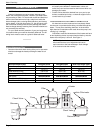
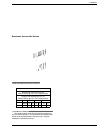
HEAT EXCHANGER PRESSURE DROP TABLE
Table 7. 130A Pressure Drop Table.
FLOW (GPM) PRESSURE DROP (FT. OF HEAD)
20 5.5
30 8.3
40 8.4
50 8.5
60 8.6
70 8.7
80 10.0
90 12.5
100 14.5