


page
9
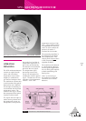
XP95 Optical Smoke Detector ▲ Part Number 55000-600
OPERATING
PRINCIPLES
The XP95 optical detector
uses the same outer case as
the ionisation smoke detector
and is distinguished by the
indicator LED which is clear
in standby and red in alarm.
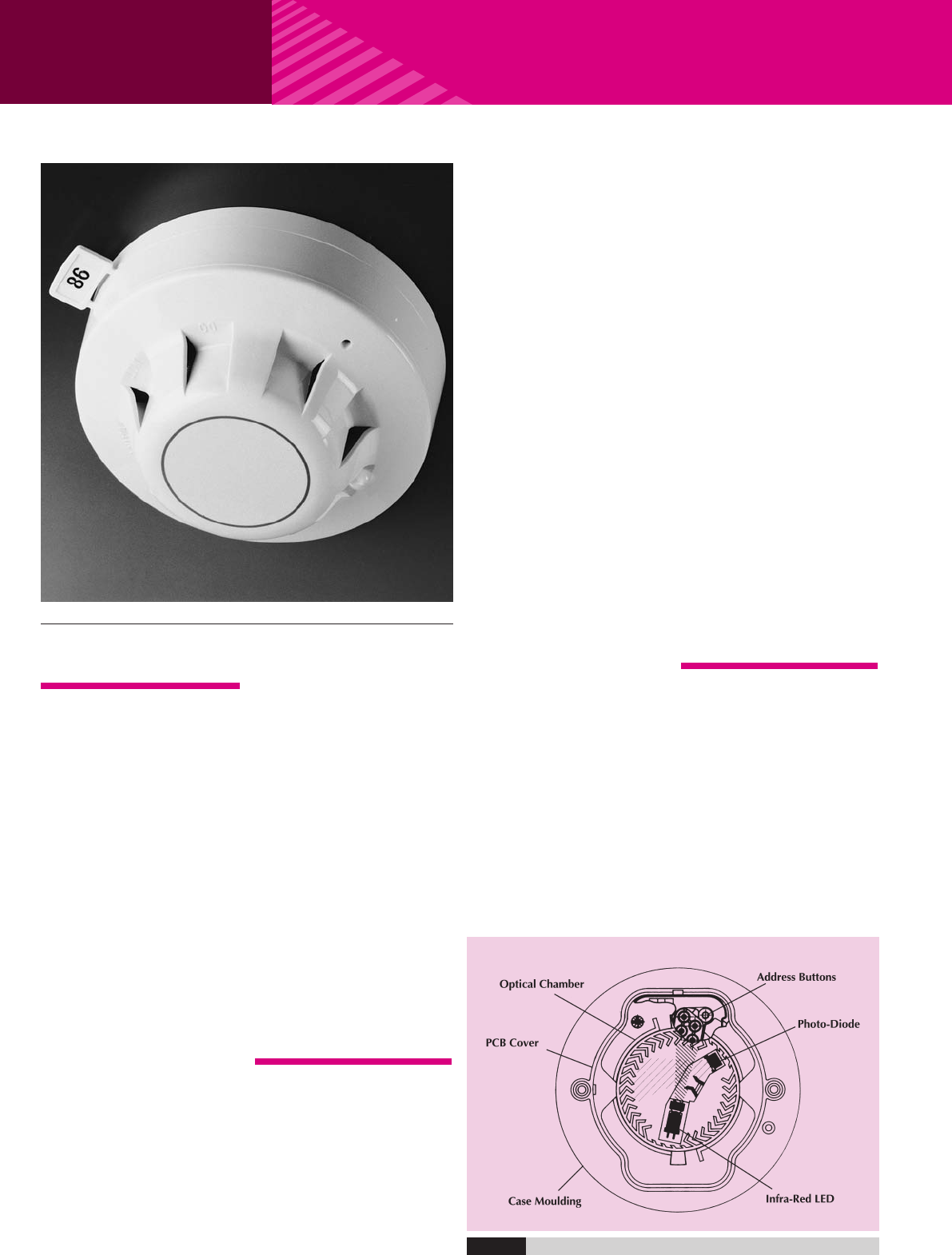
Within the case is a printed
circuit board which on one
side has the light proof
labyrinth chamber with
integral gauze surrounding
the optical measuring system
and on the other the address
capture, signal processing and
communications electronics.
An infrared light emitting
diode within its collimator is
arranged at an obtuse angle
to the photo-diode. The
photo-diode has an integral
daylight-blocking filter.
The IR LED emits a burst of
collimated light every second.
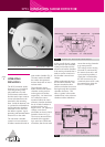
Fig.7 Top section - XP95 Optical Smoke Detector
In clear air the photo-diode
receives no light directly
from the IR LED because of
the angular arrangement
and the dual mask. When
smoke enters the chamber
it scatters photons from the
emitter IR LED onto the
photo-diode in an amount
related to the smoke
characteristics and density.
The photo-diode signal is
processed by the optical
ASIC and passed to the A/D
converter on the
communications ASIC ready
for transmission when the
device is interrogated.
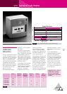
ELECTRICAL
DESCRIPTION
The detector is designed to
be connected to a two wire
loop circuit carrying both
data and a 17V to 28V dc
XP95 OPTICAL SMOKE DETECTOR
supply. The detector is
connected to the incoming
and outgoing supply via
t
erminals L1 and L2 in the
mounting base. A remote
LED indicator requiring not
more than 4mA at 5V may
be connected between the
+R and -R terminals. An
earth connection terminal is
also provided.
When the device is energised
the ASICs regulate the flow
of power and control the
data processing. The optical
ASIC is controlled by the
communications ASIC and
pulses the IR LED. The signal
from the photo-diode is
processed by the optical
ASIC and transferred to
the A/D converter in the
communications ASIC
where it is then stored.
When smoke enters the
chamber the photo-diode
signal increases. The
information to the A/D
converter is updated once
per second or when either
the monitor or the preceding
address is interrogated.
Whenever the device is
interrogated this data is sent
to the control equipment.
EN54 threshold alarm levels
are calibrated within the
processing ASIC. If the
d
evice is not addressed
within 1 second of its last
polling and the analogue
value is greater than the
EN54 alarm level the alarm
f
lag is initiated and the
device address is added to
the data stream every 32
polling cycles from its last
polling for the duration of
the alarm level condition,
except when the alarming
device is being interrogated.
This can provide a location
identified alarm from any
device on the loop in
approximately 2 seconds.
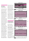
The detector is calibrated to
give an analogue value of
25±7 counts in clean air.
This value increases with
smoke density. A count of 55
corresponds to the EN54 alarm
sensitivity level. See Fig.9.
ENVIRONMENTAL
CHARACTERISTICS
The XP95 optical smoke
detector is unaffected by
wind or atmospheric
pressure and operates over
the temperature range -20°C
to +60°C. See Fig. 10.