


page
6
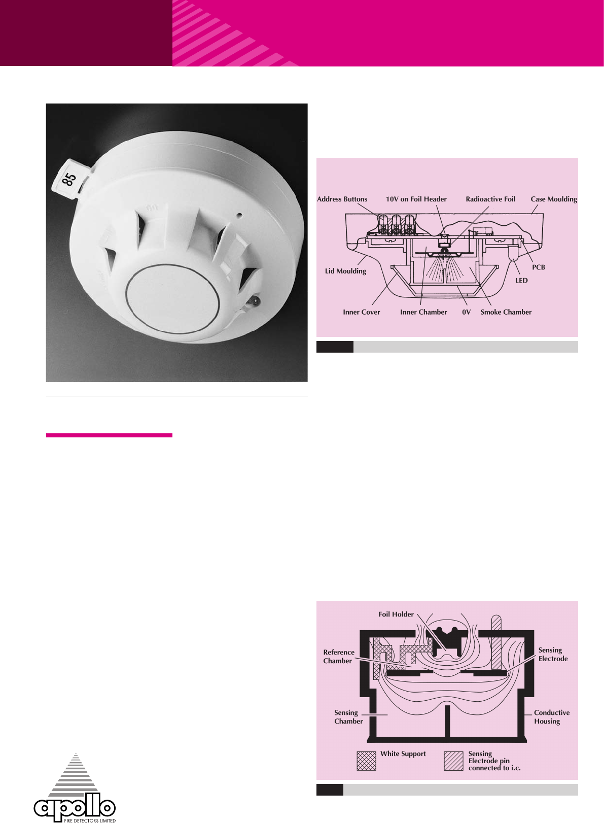
is that a small electric current
flows between the electrodes.
At the junction between the
reference and smoke chambers
is the sensing electrode that is
used to convert variations in
the chamber currents into a
voltage.
When smoke particles enter
the ionisation chamber, ions
become attached to them
with the result that the current
flowing through the ionisation
chamber decreases. This
effect is greater in the smoke
chamber than in the reference
chamber and the imbalance
causes the sensing electrode
to go more positive.
The voltage on the sensing
electrode is monitored by
the sensor electronics and
is processed to produce a
signal that is translated by
the A/D converter in the
communications ASIC ready
for transmission when the
device is interrogated.
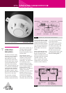
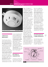
XP95 IONISATION SMOKE DETECTOR
XP95 Ionisation Smoke Detector ▲ Part Number 55000-500
OPERATING
PRINCIPLES
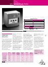
The XP95 ionisation smoke
detector has a moulded
self-extinguishing white
polycarbonate case with
wind resistant smoke inlets.
Stainless steel wiper contacts
connect the detector to the
terminals in the mounting
base. Inside the detector case
is a printed circuit board that
has the ionisation chamber
mounted on one side and
the address capture, signal
processing andcommunications
electronics on the other.
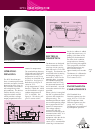
The ionisation chamber
system is an inner reference
chamber contained inside an
Fig.1 Sectional view - XP95 Ionisation Smoke Detector
outer smoke chamber (Fig 1).
The outer smoke chamber
has smoke inlet apertures
that are fitted with an insect
resistant mesh.
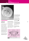
The radioactive source
holder and the outer smoke
chamber are the positive
and negative electrodes
respectively. An Americium
241 radioactive source
mounted within the inner
reference chamber irradiates
the air in both chambers to
produce positive and
negative ions. On applying a
voltage across these
electrodes an electric field is
formed as shown in Fig 2.
The ions are attracted to the
electrode of the opposite
sign, some ions collide and
recombine, but the net result
Fig.2 DiagramshowinglinesofequipotentialfortheXP95IonisationSmokeMonitor