


page
15
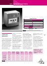
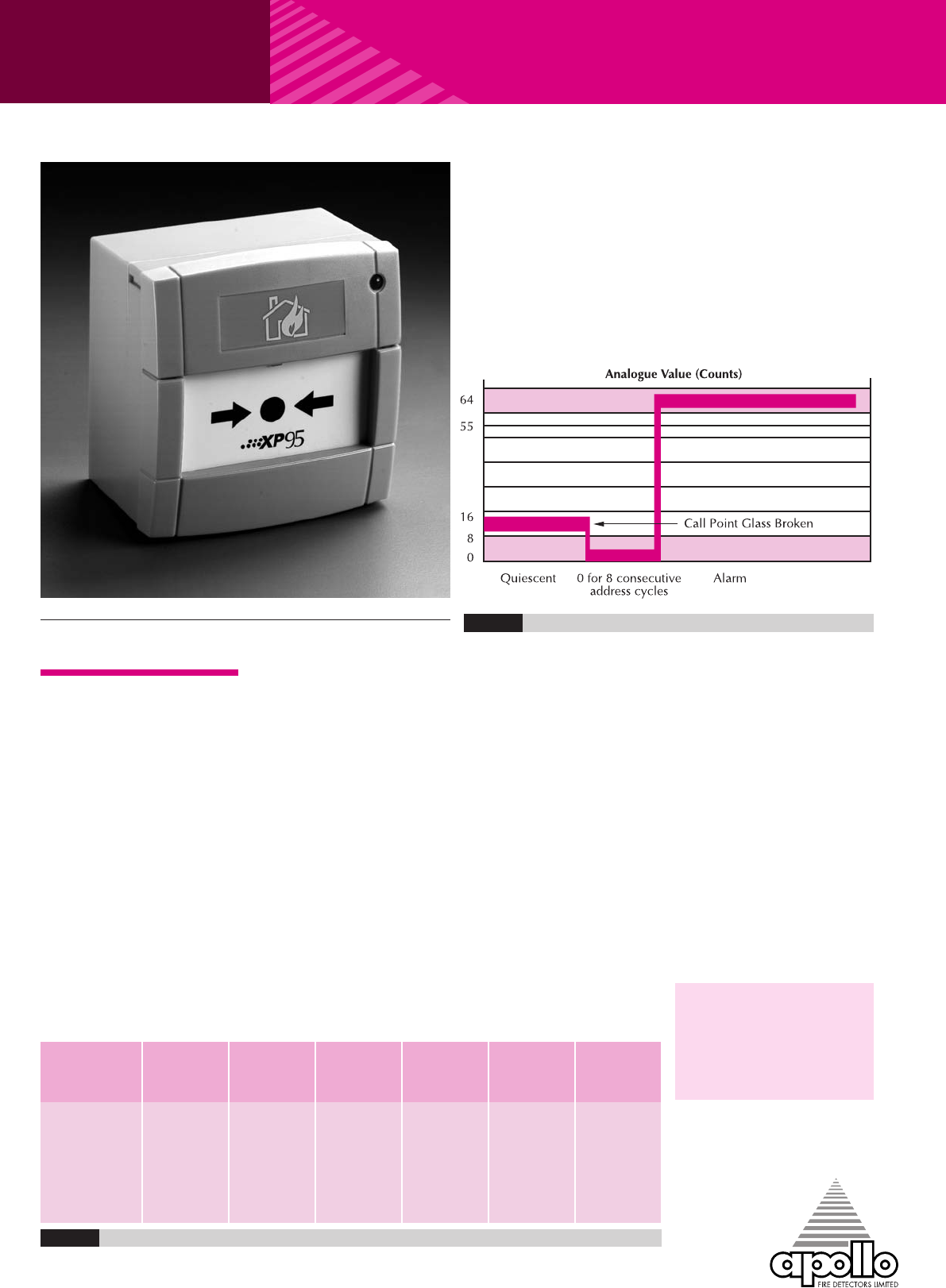
means of a seven-segment
DIL switch.
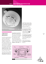
A single bi-coloured alarm
LED is provided on the call
point. This LED is controlled,
independently of the call
point, by the control panel.
The red LED is lit when the
call point has been activated.
An amber/yellow LED
indicates a fault.
Call points can be remotely
tested from the panel by
transmission of a single bit
in the communications
protocol. Call points
respond by providing a
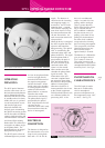
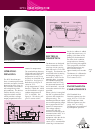
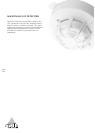
XP95 MANUAL CALL POINT
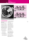
XP95 Manual Call Point (MCP)
OPERATING
PRINCIPLES
The new Apollo XP95 EN54-
11:2001 compliant Manual
Call Point (MCP) is based on
the KAC conventional MCP
range. It is electronically
and mechanically backward
compatible with previous
Apollo call points based on
KAC’s World Series product.
The address of each call
point is set at the
commissioning stage by
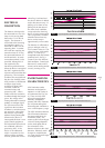
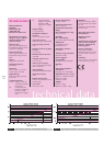
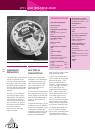
Fig.16 Typicalresponsecharacteristic -XP95ManualCall Point
value of 64 which
corresponds to the alarm
value. The panel should
recognise this response as a
test signal and should not
raise a general alarm.
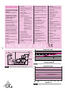
XP95 Manual Call Points are
available with or without an
isolator. Each version is
available with a resettable
element and a backbox for
surface mounting as standard.
If a glass or flush mounting
tray is required, these are
available on request.
Versions with a pattress box
are also available with and
without an isolator. For all
part numbers please refer to
Table 2.
To provide additional
protection against accidental
operation, a transparent
hinged cover with a locking
tag, part number 26729-152
is available, which can be
fitted to the manual call
point. Please note that the
call point dos not conform
to EN54-11:2001 when this
lid is fitted and secured with
the locking tag.
Important Note – the use
of lubricants, cleaning
solvents or petroleum
based products should be
avoided.
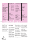
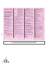
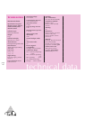
Colour Deformable Backbox Pattress Isolated Non-
Element for surface Box isolated
Wiring
55100-905 Red •• •
55100-907 Red •••
55100-908 Red •• •
55100-909 Red •••
Table2