


8
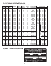
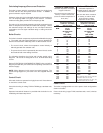
ELECTRICAL CONFIGURATION TABLE
Boiler Type Voltage Between Control Elements
Nameplate of Boiler Terminal Circuit Quantity Element
Markings Service Lugs Voltage Per Operating
Voltage Phase (1 Phase) Contractor Voltage
1
120 1 208
208
3 Delta
(With 120 1 208
Neutral)
1 120 1 240
240
3 Delta 120 1 240
480 3 Wye* 120 1 or 2 277
480 3 Delta 120 1or 2 480
* Neutral lug not necessary and not furnished due to three wire wye connection. This means only three wires (no neutral)
brought to boiler due to method of element connection. Elements operate at 277 volts.
Voltage from a conductor to ground (electrical raceway and water pipes) is not measured.
No ground lug furnished. If required installer can provide locally.
L1 L2 N G
208
120
L1 L2 L3 N G
208
208
208
120
L1 L2 G
240
240
240
240
L1 L2 L3 G
480
480
480
L1 L2 L3 G
480
480
480
L1 L2 L3 G
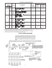
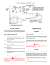
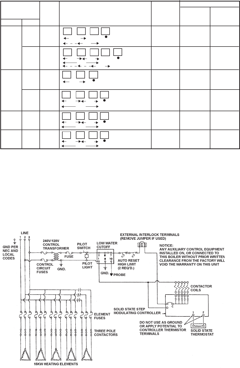
WIRING DIAGRAM 208V OR 240V THREE-PHASE (DELTA) WITH STEP CONTROL
TYPICAL WIRING DIAGRAMS
The following wiring diagrams are included in this manual to show
typical arrangements of electrical components in the control and
power circuits by voltage and phase charactreristics. They are
to be used as a reference by the installer or servicer in performing
their work. A diagram of the boiler wiring is furnished with the
boiler.