


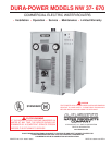

7
Calculating Amperage/Overcurrent Protection
The boiler is factory wired for connection to three wire single-phase
or three and four wire three-phase branch circuits. In addition, a
ground conductor may be required.
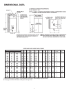
A diagram of the wiring is furnished with the boiler for the electrician’s
use. An amperage table is on page 4 of this manual. The boiler
model and rating plate provides full load amperage data.
The rating of the overcurrent protection should be computed on the
basis of 125 percent of the total connected load amperage. Where
the standard ratings and settings do not correspond with this
computation, the next higher standard rating or setting should be
selected.
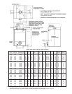
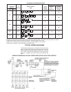
Boiler Circuits
The boiler’s electrical components are pictured and identified on page
5. The model and rating plate illustration on page 4 identifies the
electrical characteristics. Basically, there are two electrical circuits:
• The control circuit, where the temperature control directly or
indirectly operates the contactor coils.
• The power circuit, which is operated by the control circuit, carries
the electrical load of the heating elements.
The following describes the circuits and includes typical wiring
diagrams. All circuits are designed for 60 or 50 Hertz alternating
current.
Refer to ELECTRICAL CONFIGURATION TABLE, below, and wiring
diagram provided with your boiler before completing connections to
electrical supply.
NOTE: Wiring diagrams in this manual are typical examples. The
specific wiring diagram for your boiler is the one supplied with the
boiler.
Control Circuit
All control circuits are operated on single-phase 120V. A transformer
is used in the control circuit.
Control circuit wiring is 14 Awg, THHN or THWN type, rated 600 volts,
105°C.
Seperate instructional literature is provided with the boiler for the
modulating solid state step control.
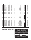
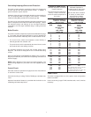
Portion of Table 310-16
Allowable Ampacities of Insulated
Copper Conductors
Not more than three conductors in
raceway or cable or direct burial
(based on ambient temperature of
30°C, 86°F.)
Portion of Table 310-16
Allowable Ampacities of
Insulated Aluminum and Copper-
Clad AluminumConductors
Not more than three conductors
in raceway or cable or direct
burial (based on ambient
temperature of 30°C, 86°F.)
Temperature Rating of Temperature Rating of
Conductor. See Table Conductor. See Table
Size 310-13 in Code Size 310-13 in Code
AWG 75°c AWG 75°C
MCM (167°F) MCM (167°F)
TYPES TYPES
RH, RHW, RUH RH, RHW, RUH
(14-2), (12-2),
THW, THWN, THW, THWN,
XHHW, USE XHHW, USE
18 - - - - - 12 15
16 - - - - - 10 25
14 15 8 40
12 20 6 50
10 30 4 65
845 3 75
665 2 90
4 85 1 100
3 100 1/0 120
2 115 2/0 135
1 130 3/0 155
1/0 150 4/0 180
2/0 175 250 205
3/0 200 300 230
4/0 230 350 250
250 255 400 270
300 285 500 310
350 310 600 340
400 335 700 375
500 380 750 385
600 420 800 395
700 460 900 425
750 475 1000 445
800 490 1250 485
900 520 1500 520
1000 545 1750 545
1250 590 2000 560
1500 625
1750 650
2000 665
These capacities relate only to conductors
described in Table 310-13 in Code.
For ambient temperatures over 30°C, see
Correction Factors, Note 13 in Code
Power Circuit
The boiler is equipped with one of the power circuit configurations
shown in the table.
Power circuit wiring is type THHN, rated 600 volts, 105°C, sized as
necessary.