


6
IMPORTANT
IT IS RECOMMENDED THAT A QUALIFIED SERVICE TECHNICIAN
PERFORM THE INITIAL FIRING OF THE BOILER. AT THIS TIME
THE USER SHOULD NOT HESITATE TO ASK THE TECHNICIAN
ANY QUESTIONS WHICH THEY MAY HAVE IN REGARD TO THE
OPERATION AND MAINTENANCE OF THE BOILER.
BEFORE FILLING THE SYSTEM FOR OPERATION the hot water
system should be internally cleaned and flushed to remove any
contaminants which may have accumulated during installation. See
section of this manual titled SYSTEM CLEANING.
RELIEF VALVE
An ASME rated pressure relief valve is furnished with the boiler. A
fitting for the relief valve is provided in the top of the boiler. A drain
line from the relief valve should terminate near a suitable drain. Do
not thread, plug, or cap the end of the drain line.
The pressure setting of the relief valve should not exceed the pressure
capacity of any component in the system including the boiler.
HIGH TEMPERATURE DEVICES
Automatic Device
The boiler control circuit contains a high temperature cutoff switch.
This device shuts off the heating elements if excessive water
temperatures are reached. The high temperature cutoff has an
adjustable range of 100° to 240°F and automatically resets on a drop
of temperature.
Manual Device
A manual reset high limit will be in the control circuit in addition to the
automatic device previously described. The control has an adjustable
range of 110° to 290°F and must be manually reset after a drop of
temperature.
Reset button is located under the right side panel of the boiler.
Disconnect the power before removing the panel to push the button.
INSTALLATION
REQUIRED ABILITY
INSTALLATION OR SERVICE OF THIS BOILER REQUIRES ABILITY
EQUIVALENT TO THAT OF A LICENSED TRADESMAN IN THE
FIELD INVOLVED. PLUMBING AND ELECTRICAL WORK ARE
REQUIRED.
GENERAL
Do not test electrical system before boiler is filled with water, follow
START UP procedure in this manual.
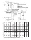
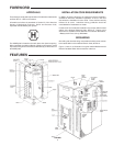
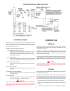
The principal components of the boiler are identified in Figure 1. The
model and rating plate, see illustration on page 4, provides certain
useful information required at installation. Both of these references
should be used to identify the boiler and its components.
Water boilers are usually placed in series with the heating system on
the outlet side of the circulating pump. The boiler piping should include
inlet and outlet water valves to permit maintenance and service work
to be performed without disturbing the rest of the system.
Detailed system installation drawings are normally provided by the
equipment purchaser or system designer.
LOCATING THE BOILER
For the best installation, the boiler should be located:
1. On a level surface.
• Shim the channel type skid base as necessary if leveling
is required.
2. Near a floor drain.
• The boiler should be located in an area where leakage of
the tank or connections will not result in damage to the
area adjacent to the boiler or to lower floors of the
structure. When such locations cannot be avoided, a
suitable drain pan should be installed under the boiler.
The pan should be at least two inches deep, have a
minimum length and width of at least two inches greater
than the dimensions of the boiler and should be piped to
an adequate drain.
• The discharge opening of the relief valve should always
be piped to an open drain.
3. Suggested clearances from adjacent surfaces are found on a label
attached to the control compartment door.
• UL minimum clearances:
- 24” all sides
- 12” top
• Allow clearance for hinged control compartment doors.
• Elements can be changed with 24” clearance.
4. The boiler may be installed in a confined space if adequate
ventilation is provided.
ELECTRICAL
General
Check the boiler model and rating plate information against the
characteristics of the branch circuit electrical supply. Do not connect
the boiler to an improper source of electricity.
Voltage applied to the boiler should not vary more than + 5% to -10%
of the model and rating plate marking for satisfactory operation.
Do not energize the branch circuit for any reason before the boiler is
filled with water. Doing so may cause the heating elements to burn
out. Such damage is not covered under the terms of the warranty.
The branch circuit is connected to the block through an opening
provided on top of the boiler.
The boiler should be connected to a separate, grounded, branch circuit
with overcurrent protection and disconnect switch. These are part of
the electrical supply system not components of the boiler, as such
they are obtained locally. The boiler should be grounded in accordance
with national and local codes.
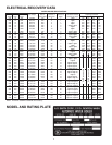
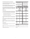
Branch Circuit
The branch circuit wire size should be established through reference
to the National Electrical Code or other locally approved source in
conjunction with boiler amperage rating. Branch circuit wiring which
connects to the boiler terminal block should be temperature rated at
75°C. For convenience, portions of the wire size tables from the
Code are reproduced here. It is suggested the electrician size the
branch circuit at 125 percent of the boiler rating and further increase
wire size as necessary to compensate for voltage drop in long runs.
Branch circuit voltage drop should not exceed 3% at the boiler.