


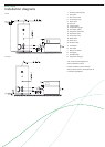
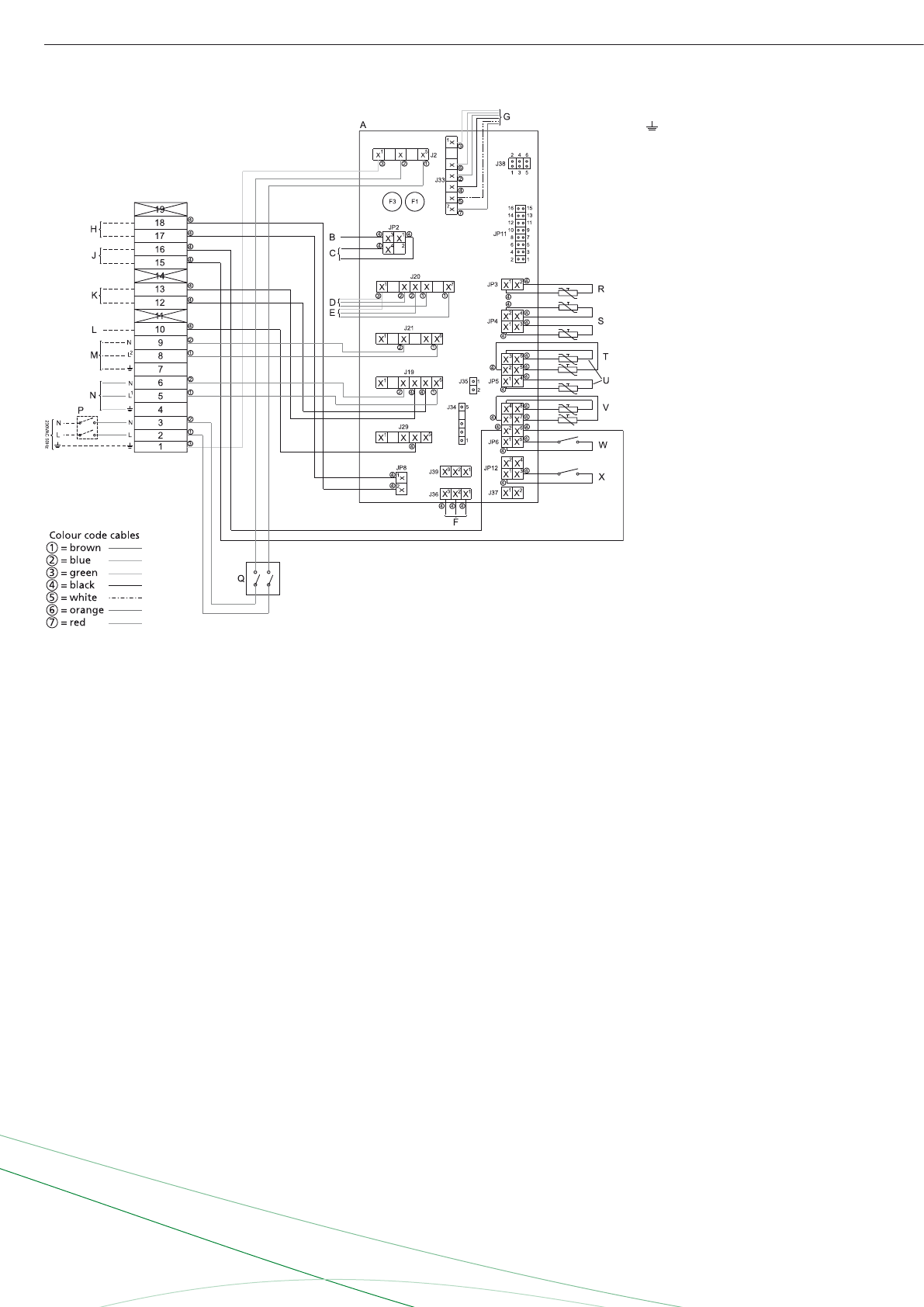
TERMINAL STRIP CONNECTIONS
Earth
N Neutral
L Phase input of controller
L1 Phase input of system pump
L2 Phase input of program-controlled
pump
COMPONENTS
A Controller
B Ionisation rod
C Glow igniter
D Gas control 1
E Gas control 2
F Display
G Fan
H External on/off
J n/a
K Error signal
L n/a
M Optional pump
N System pump
P Double-pole mains switch
Q I/O switch control
R Temperature sensor
(T1 - inlet heat exchanger)
S Dummy
T Temperature sensor (T3 - Tank)
U Temperature sensor
(T2 - outlet heat exchanger)
V Selection resistor
W Air pressure switch
X Flow switch
CONTROLLER CONNECTIONS
J2 Connector for power supply
to controller
J19 Connector for system pump
J20 Connector for gas control
J21 Connector for program-controlled
pump and error signal
J29 Connector for room-thermostat
(230VAC)
J33 Connector for fan control signal
J36 Connector for display to controller
JP2 Connector for ionisation rod
and glow igniter
JP3 Connector for temperature sensor T1
JP4 Connector for dummy
JP5 Connector for temperatures
sensors T2 and T3
JP6 Connector for selection resistor,
air pressure switch
JP8 Connector for extra
ON mode switch
JP12 Connector for flow switch
F1 Fuse
F3 Fuse
Burkay - Genesis
Electrical scheme