


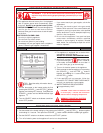
2
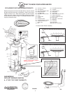
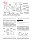
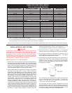
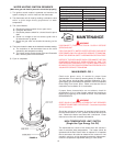
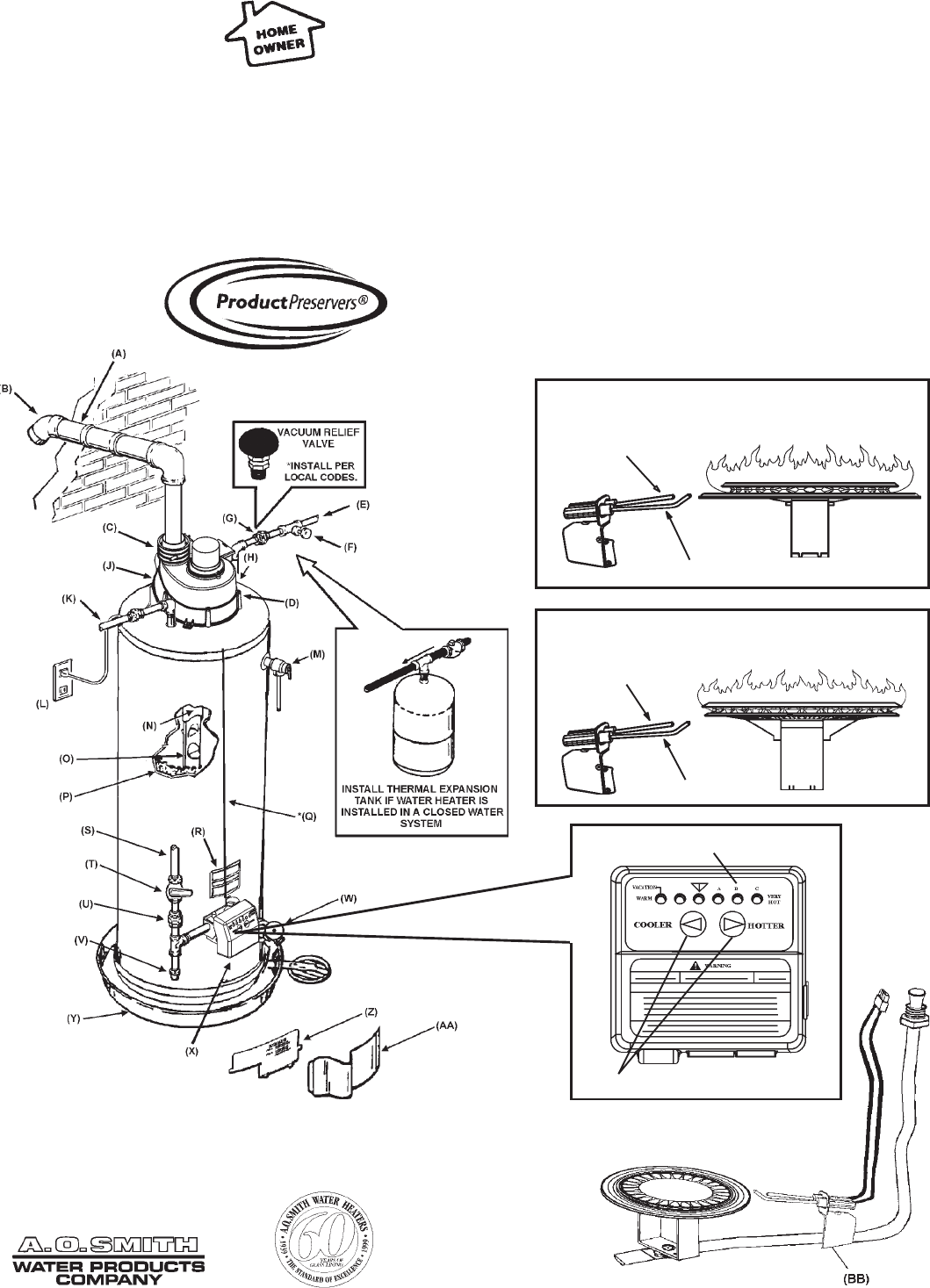
GET TO KNOW YOUR WATER HEATER
(A) Vent Pipe - Exhaust
(B) Vent Terminal
(C) Vent Adapter-Rubber Boot
(D) Blower Assembly
(E) Cold Water Inlet
(F) Inlet Water Shut-off Valve
(G) Union
(H) Inlet Dip Tube
(J) Anode**
(K) Hot Water Outlet
(L) Oulet Receptacle (115 VAC)
(M) Temperature-Pressure
Relief Valve
(N) Flue
REPLACEMENT PARTS AND DELIMING PRODUCTS
Replacement parts and recommended delimer may be ordered
through authorized servicers or distributors. Refer to the Yellow
Pages for where to call. When ordering parts, provide complete
model and serial numbers (see rating plate), quantity and name
of part desired (as listed in Figure 1). Standard hardware items
may be purchased locally.
GAS MODELS
WITH HOT SURFACE IGNITION
& - 2" OR 3" PVC VENT CAPABILITY
FIGURE 1
(O) Flue Baffle Assembly**
(P) Insulation
(Q) Control Harness
(R) Rating Plate
(S) Gas Supply
(T) Manual Gas Shut-off Valve
(U) Ground Joint Union
(V) Dirt Leg (Sediment Trap)
(W) Drain Valve
(X) Gas Valve - Thermostat
(Y) Drain Pan
(Z) Inner Door
(AA) Outer Door
(BB) HSI Burner Assembly
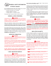
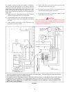
*CAUTION: 115VAC IN CONTROL HARNESS
AND INSIDE OUTER DOOR
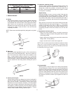
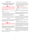
NATURAL HOT SURFACE IGNITER & MAIN BURNER
HOT
SURFACE
IGNITOR
SENSOR
PROPANE HOT SURFACE IGNITER & MAIN BURNER
TEMPERATURE INDICATORS
TEMPERATURE ADJUSTMENT BUTTONS
HOT
SURFACE
IGNITOR
SENSOR
**Located Under Blower Assembly