


7
WARNING
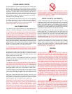
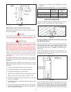
VENT TERMINATION MUST NOT BE WITHIN 4 FEET (122 cm)
OF ANY ITEMS SUCH AS GAS METERS, GAS VALVES OR OTHER
GAS REGULATING EQUIPMENT.
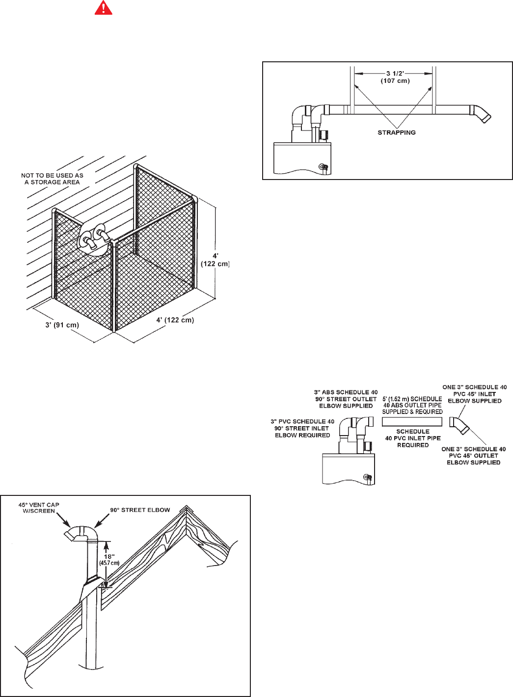
WIRE FENCE
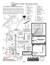
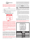
When the water heater outlet terminal is low enough to be touched
accidentally, or is accessible to small children, a wire mesh
chain link fence (as show in Figure 7) may be used. Care should
be taken to maintain adequate ventilation around the outlet
terminal. If a chain link fence is installed, it must not be used as
a storage area for items that may block proper ventilation.
FIGURE 7.
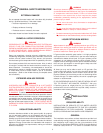
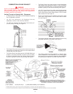
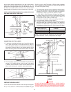
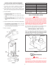
Venting Through Roof - Clearances
• 0" clearance for 3" PVC, ABS, or CPVC Schedule 40 piping
from combustible and noncombustible surfaces.
• The vent exhaust outlet and air inlet terminals shall terminate at
least 18 inches (45.7 cm) above the roof surface, see Figure 8.
• The venting system must be installed in a manner which
allows inspection of the installation of the venting pipes and
joints as well as periodic inspection after installation as
required by ANSI Standards.
AIR FOR VENTILATION FOR APPLIANCES
LOCATED IN CONFINED SPACES
Air for ventilation should be provided if installed in a confined
space. Refer to the National Fuel Gas Code, ANSI Z223.1.
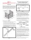
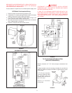
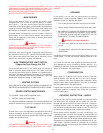
FIGURE 9.
Horizontal runs must be securely supported at 3 1/2 foot (8.9 cm)
intervals and vertical runs supported at 5 foot (1.5 cm) intervals.
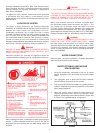
VENTING THROUGH AN OUTSIDE WALL
A. ALL 75 GAL. (283.9L) 65,000 & 70,000 BTU/HR MODELS & 50
GAL. (189.3L) 60,000 & 65,000 BTU/HR MODELS, SEE FIGURE 10.
In the carton is supplied:
1. Two 3" inlet and outlet PVC Schedule 40 - 45° vent caps.
2. A 3" ABS Schedule 40 - 90° street elbow; used to connect the
outlet vent pipe to the water heater when the outlet vent pipe
is to be turned horizontally directly off the blower.
3. A 5' (1.52 m) section of 3" ABS Schedule 40 outlet vent pipe
(more may be required and must be supplied locally).
FIGURE 10. HI BTU MODELS.
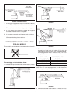
1. The water heater requires its own (separate) venting system.
2. Only 3" ABS Schedule 40 piping & fittings are acceptable
materials on the first 5' of outlet vent system. This applies to only 50
gal. (189.3 L) Hi BTU input models and all 75 gal. (283.9 L) models.
3. 3" PVC, ABS, or CPVC Schedule 40 piping & fittings are
acceptable materials for the inlet vent system and for the
outlet vent system after the first 5' (1.52 m).
4. It cannot be connected to existing vent piping or chimney.
5. When venting through an outside wall, the vents must
terminate horizontally to the outdoors.
B. ALL 50 GAL. (189.3 L) 38,000 AND 40,000 BTU/HR MODELS & 40
GAL. (151.4 L) 36,000 & 40,000 BTU/HR MODELS, SEE FIGURE 11.
In the carton is supplied:
1. Two 3" inlet and outlet PVC Schedule 40 - 45° vent caps.
All other piping must be supplied by the supplier.
FIGURE 8.