


10
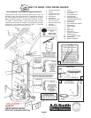
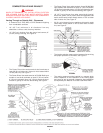
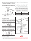
wall will help minimize discoloration of the wall. Note that the
inside flue mounting adaptors must be slipped over the vent
piping before locating the pipe through the wall. Before securing
the inside and outside collars to the wall, use a silicone sealer
between pipe and opening to insure a water and air tight seal.
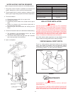
INSTALLATION SHOWING USE OF PVC, ABS OR CPVC PIPE
FOR INLET AND OUTLET VENT PIPE.
FIGURE 20.
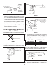
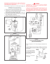
CONNECTING VENT TO BLOWER
1. If making an immediate horizontal run of vent off the blower,
one 3" PVC inlet and one 3" PVC (ABS for 50 Gal. (189.3 L)
and 75 Gal.(283.9 L) Models) outlet Schedule 40 street elbows
are required. Place the elbow in the required direction on the
blower and using three sheet metal screws, attach the elbow.
FIGURE 21.
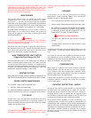
2. If there is to be a vertical run from the blower, the 3" PVC inlet
and the 3" PVC (ABS for 50 Gal. (189.3 L) and 75 Gal.(283.9
L) Models) outlet Schedule 40 pipe must be attached to the
blower and venting hood, using six sheet metal screws.
FIGURE 22.
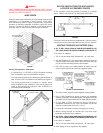
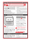
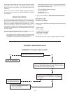
VENTING THROUGH A ROOF
Two 3" inlet and outlet PVC Schedule 40-45° vent caps are supplied.
A 5' (1.52 m) section of 3" ABS Schedule 40 outlet vent pipe
(50 Gal. (189.3 L) Hi BTU input & all 75 Gal. (283.9 L) Models
only) is supplied on certain models only. (More may be required
and must be supplied locally).
1. The water heater requires its own (separate) venting system.
2. Only 3" ABS Schedule 40 piping and fittings are acceptable
materials on the first 5' (1.52 m) of the outlet vent system for
some 50 Gal. (189.3 L) and 75 Gal. (283.9 L) models.
3. 3" PVC, ABS, or CPVC Schedule 40 piping and fittings are
acceptable materials for the inlet vent system and for the outlet
vent system (after the first 5' (1.52 m) for 50 Gal. (189.3 L) Hi
BTU input and 75 Gal. (283.9 L) Models only).
4. It cannot be connected to existing vent piping or chimney.
5. It must terminate vertically to the outdoors.
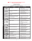
6. The total vertical and horizontal runs cannot exceed the
maximum length with a maximum number of 90° elbows as
specified in the table below. If more elbows are required, the
venting distance must be reduced 5' (1.52 m) for every 90° elbow.
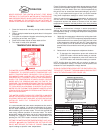
3" DIA. VENTS NUMBER OF 90° DEG.
MAX. LENGTH (FT.) ELBOWS*
45 (13.72 m) 1
40 (12.2 m) 2
35 (10.7 m) 3
*NOTE: Two 45° elbows are equivalent to one 90° elbow. One
90° elbow equals 5' (1.52 m) of equivalent vent length.
FIGURE 23.
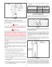
WIRING
DANGER
DO NOT USE AN EXTENSION CORD. IF THERE IS NOT A
SUITABLE RECEPTACLE AND/OR LOCAL CODES PROHIBIT
USE OF A POWER CORD, FIELD WIRING MUST BE PROVIDED.
THE APPLIANCE, WHEN INSTALLED, MUST BE ELECTRICALLY