


6
COMBUSTION AIR AND EXHAUST
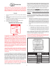
WARNING
WHEN DETERMINING THE INSTALLATION LOCATION
FOR A POWER DIRECT VENT WATER HEATER, SNOW
ACCUMULATION AND DRIFTING SHOULD BE CONSIDERED
IN AREAS WHERE APPLICABLE.
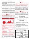
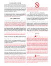
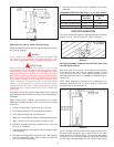
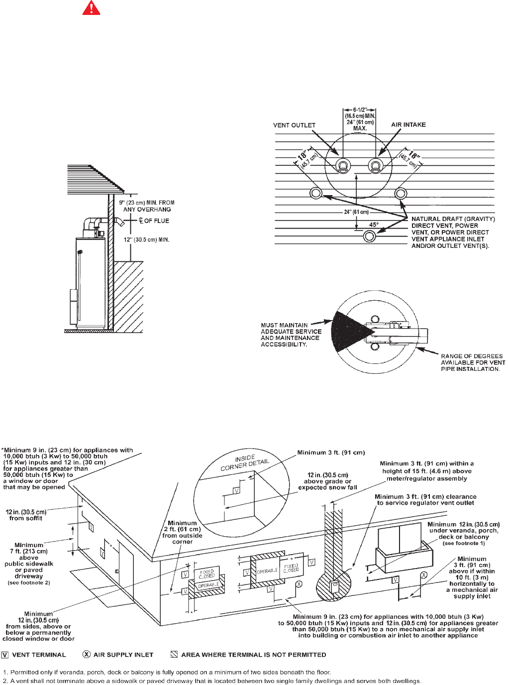
Venting Through an Outside Wall - Clearances
• 0" clearance for 3" PVC, ABS, or CPVC Schedule 40 piping
from combustible surfaces.
• 18" (45.7 cm) minimum in all directions from any
obstruction, such as a wall, that may interfere.
• 12" (30.5 cm) minimum from the ground and corners, 9"
(23 cm) ceiling overhang, see Figure 3.
FIGURE 3.
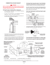
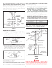
• The Power Direct Vent outlet terminal shall terminate at
least 36" (91 cm) above any forced air inlet located within
10 feet (305 cm), see Figure 4.
• The Power Direct Vent outlet terminal of 50,000 BtuH input
models or less shall terminate at least 9" (23 cm) below,
9" (23 cm) horizontally from or 9" (23 cm) above any door,
window or gravity air inlet into the building, see Figure 4.
• The Power Direct Vent outlet terminal of over 50,000 BtuH
input models shall terminate at least 12" (30.5 cm) below,
12" (30.5 cm) horizontally from or 12" (30.5 cm) above any door,
window or gravity air inlet into the building, see Figure 4.
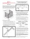
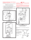
• 18" (45.7 cm) minimum from other natural draft (gravity)
direct vent, power vent or power direct vent appliance inlet
and/or outlet vent(s) when directly above or 135° to either
side of center line, see Figure 5.
• 24" (61 cm) minimum from any appliance inlet and/or outlet
vents when directly below or 45° to either side of center
line, see Figure 5.
FIGURE 5.
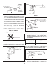
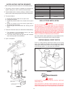
• The location selection must provide clearances for servicing
and proper operation of the water, see Figure 6.
FIGURE 6.
• The venting system must be installed in a manner which
allows inspection of the installation of the venting pipes
and joints as well as periodic inspection after installation
as required by the National Fuel Gas Code ANSI Z223.1.
FIGURE 4.