


12
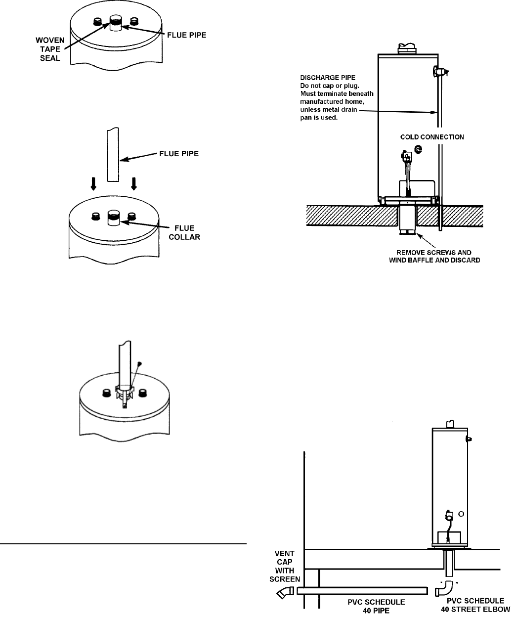
FIGURE 16.
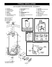
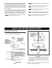
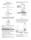
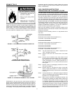
7. Extend the fl ue pipe down close to the water heater fl ue collar,
see Figure 17.
FIGURE 17.
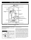
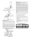
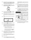
8. Slide the securing clamp over the bottom of the fl ue pipe and pull
the pipe down over the fl ue collar. Locate vent securing clamp in
top and secure clamp with sheet metal screw. Tighten nut and
bolt clamp until fl ue pipe is tight in clamp, see Figure 18.
FIGURE 18.
NOTE: All joints for vent piping between roof jack and water heater
are sealed from the manufacturer. No additional sealing of vent pipe
is necessary.
MANUFACTURED HOME INSTALLED OVER
BASEMENT OR CRAWLSPACE - AIR INTAKE
THROUGH AN OUTSIDE WALL
ALL 30 AND 40 GALLON (113.56 AND 151.42 LITER) MODELS
3” (7.62 cm) PVC Schedule 40 intake air vent piping:
Optional Kit No. 9002986005 contains a 3” (7.62 cm) PVC Schedule
40-45° vent cap with screen and two 3” (7.62 cm) wall collars.
ALL 50 GALLON (189.27 LITER) MODELS
4” (10.16 cm) PVC Schedule 40 intake air vent piping:
Optional Kit no. 9002987005 contains a 4” (10.16 cm) PVC Schedule
40-45° vent cap with screen and two 4” (10.16 cm) wall collars.
ALL MODELS
1. PVC, ABS or CPVC Schedule 40 piping and fi ttings are acceptable
materials for the intake air vent system.
2. The intake air vent system must terminate horizontally to the
outdoors.
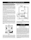
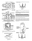
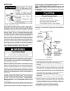
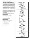
3. Remove the screws which attach the wind baffl e to the existing
metal air intake vent pipe underneath the home. Discard the wind
baffl e and screws, see Figure 19.
FIGURE 19.
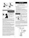
4. Attach a 3” (7.62 cm) or 4” (10.16 cm) PVC street elbow to the metal
air intake vent using 3 sheet screws. Continue PVC piping to outside
wall and terminate with vent cap and screen, see Figure 20.
3” (7.62 cm) size - 30 and 40 gallon (113.56 and 151.42 Liter) models.
4” (10.16 cm) size - 50 gallon (189.27 Liter) models.
See pages 13 and 14 for cementing instructions
FIGURE 20.
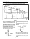
NOTE: Vent cap must be located a minimum of 12” (30.48 cm) above
the ground or anticipated snow level.
5. Vertical and horizontal runs must be securely supported at 3 1/2
foot (106.68 cm) intervals, see Figure 21.