


8
TABLE 2.
*See models and rating plate attached to the water heater for
specific model number and other detailed information.
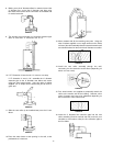
WARNING
Be sure vent pipe is properly connected to prevent escape of
dangerous flue gases which could cause deadly asphyxiation.
ALL INSTALLATIONS
For ease of assembly the installation of the various kit
combinations has been broken into individual sections.
The two steps below are common to all installations.
Once these have been performed, you need only to refer to
the type installation that pertains to you.
Installation Using Vent Kits:
1. Standard Vent Kit ..................................... Page 8
2. Optional Vertical Vent Kit ....................... Page 10
with Standard Vent Kit
3. Optional Horizontal Vent Kit ................... Page 13
4. Optional Horizontal and .......................... Page 15
Vertical Vent Kits
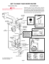
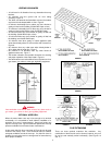
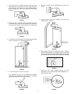
CUTTING THE OPENING THROUGH
THE OUTSIDE WALL
After thoroughly reading the “Locating the New Water Heater”
section of this manual and you have chosen a suitable water
heater installation site, use the chart below to determine
dimensions for the opening in the wall.
Cut a 6
1
/4” diameter hole completely through the outside wall.
FIGURE 13
*BTU’S in
*GAL. 1000’s
CAP. NAT/L.P. A B C
40 36/36 48-3/4 41-3/4 21
50 38/38 57-1/2 50-1/2 21
40 40/40 48-3/4 41-3/4 21
50 48/44 61 54 21
75 55 NAT. 63 54-3/4 26-1/4
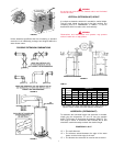
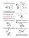
WATER HEATER ATTITUDE
There is a certain amount of variance with regard to the
direction the water heater faces.
Standing in front of the water heater (gas control facing you),
set the 3” diameter elbow (slotted end) on the flue. This will
give you a better understanding of the relation of the vent
assembly to the opening in the wall and more importantly any
possibly of interference of venting and water piping.
The direction of the water heater can now be made. Also
consider the gas control valve to insure installation, lighting,
and maintenance accessibility are retained.
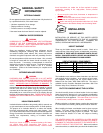
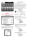
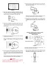
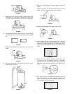
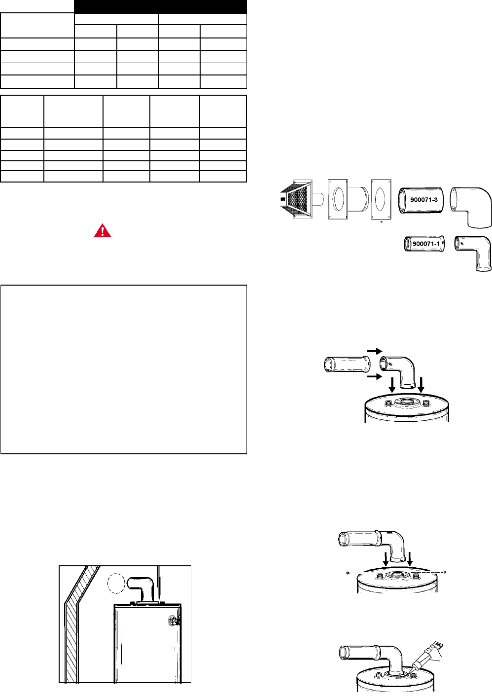
STANDARD VENT KIT
INSTALLATION #1
* Each part is stamped
with a part number.
FIGURE 14
The opening through the wall should be cut at this time. If it
hasn’t been, refer back to that section.
1. Lock the elbow to the straight 3” flue pipe. Set this
assembly in place on the end of the water heater’s flue
collar.
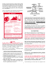
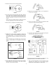
FIGURE 15
2. Mark the flue collar at the slots in the elbow. Using a
#22 drill bit, drill holes into the flue collar at the two
slots and secure the elbow to the flue collar using the
screws provided.
NOTE: Make sure elbow is properly aligned to opening in
the outside wall.
FIGURE 16
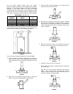
3. Using the tube of sealant supplied, run an ample amount
around the oval flare of the jacket.
FIGURE 17
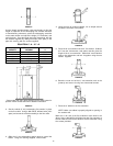
E DIMENSIONS
40-50 Gal. 75 Gal.
VENT KITS MIN. MAX. MIN. MAX.
900068-7-STD. 3-1/2 10 7/8 7-3/8
900124-6 10 15-1/2 7-3/8 12-7/8
900124-7 15-1/2 26-1/2 12-7/8 23-7/8
900124-8 26-1/2 48 23-7/8 45-3/8