


5
torque when attaching gas supply pipe to thermostat gas inlet.
The thermostat inlet has a pad for use with a backup wrench.
Apply joint compounds (pipe dope) sparingly and only to the male
threads of pipe joints. Do not apply compound to the first two
threads. Use compounds resistant to the action of liquefied
petroleum gases. Do not use teflon tape on thermostat fittings.
DISCONNECT THE APPLIANCE FROM THE GAS SUPPLY
PIPING SYSTEM DURING ANY SUPPLY PRESSURE TESTING
EXCEEDING 1/2 PSI (3.5 kPa). GAS SUPPLY LINE MUST BE
CAPPED WHEN DISCONNECTED FROM THE HEATER. FOR
TEST PRESSURES AT 1/2 PSI (3.5 kPa) OR LESS, THE
APPLIANCE NEED NOT BE DISCONNECTED, BUT MUST BE
ISOLATED FROM THE SUPPLY PRESSURE TEST BY CLOSING
THE MAIN MANUAL GAS VALVE.
BEFORE PLACING THE HEATER IN OPERATION, CHECK FOR
GAS LEAKAGE. USE SOAP AND WATER SOLUTION OR OTHER
MATERIAL ACCEPTABLE FOR THIS PURPOSE. DO NOT USE
MATCHES, CANDLES, FLAME OR OTHER SOURCES OF
IGNITION TO LOCATE GAS LEAKS.
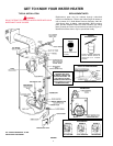
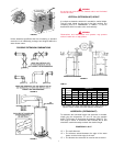
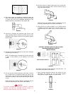
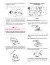
RELIEF VALVE
A NEW TEMPERATURE AND PRESSURE RELIEF VALVE
COMPLYING WITH THE STANDARD FOR RELIEF VALVES AND
AUTOMATIC GAS SHUT OFF DEVICES FOR HOT WATER
SUPPLY SYSTEMS, ANSI Z21.22 (CURRENT EDITION) MUST
BE INSTALLED IN THE HEATER IN THE MARKED OPENING
PROVIDED (SEE FIGURE 1). THE VALVE MUST BE OF A SIZE
(INPUT RATING) THAT WILL BE ADEQUATE FOR YOUR SIZE
HEATER.
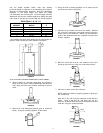
Check the metal tag on the relief valve and compare it to the
heater’s rating plate. The pressure rating of the relief valve must
not exceed the working pressure shown on the rating plate of the
heater. In addition, the hourly BTU rated temperature steam
discharge capacity of the relief valve shall not be less than the
input rating of the heater. NO VALVE IS TO BE PLACED BETWEEN
THE RELIEF VALVE AND TANK. DO NOT PLUG THE RELIEF
VALVE.
The drain line connected to this valve must not contain a reducing
coupling or other restriction and must terminate near a suitable
drain to prevent water damage during valve operation. The
discharge line shall be installed in a manner to allow complete
drainage of both the valve and line. DO NOT THREAD, PLUG OR
CAP THE END OF THE DRAIN LINE.
VENTING
WARNING
NEVER OPERATE THE HEATER UNLESS IT IS VENTED TO THE
OUTDOORS AND HAS ADEQUATE AIR SUPPLY TO AVOID
RISKS OF IMPROPER OPERATION, FIRE, EXPLOSION OR
ASPHYXIATION.
DO NOT OBSTRUCT THE FLOW OF COMBUSTION AND
VENTILATING AIR. ADEQUATE AIR FOR COMBUSTION AND
VENTILATION MUST BE PROVIDED FOR SAFE OPERATION.
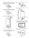
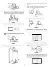
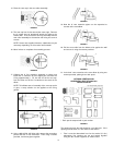
VENT PIPE TERMINATION
Before installing water heater determine placement of vent pipe
termination.
MAKE CERTAIN TO OBSERVE VENT LOCATION LIMITATION,
SEE FIG'S 4 & 5.
CAUTION
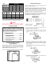
Use only the vent kit assembly supplied with this water heater or if
needed one of the three listed optional flue extensions. See
Figure 10 for possible combinations. VENTING OR
TERMINATION WITH ANY OTHER KIT NOT LISTED IS NOT
RECOMMENDED AND COULD AFFECT THE SYSTEMS
PERFORMANCE AND RESULT IN A SAFETY HAZARD.
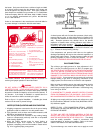
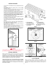
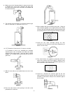
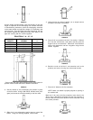
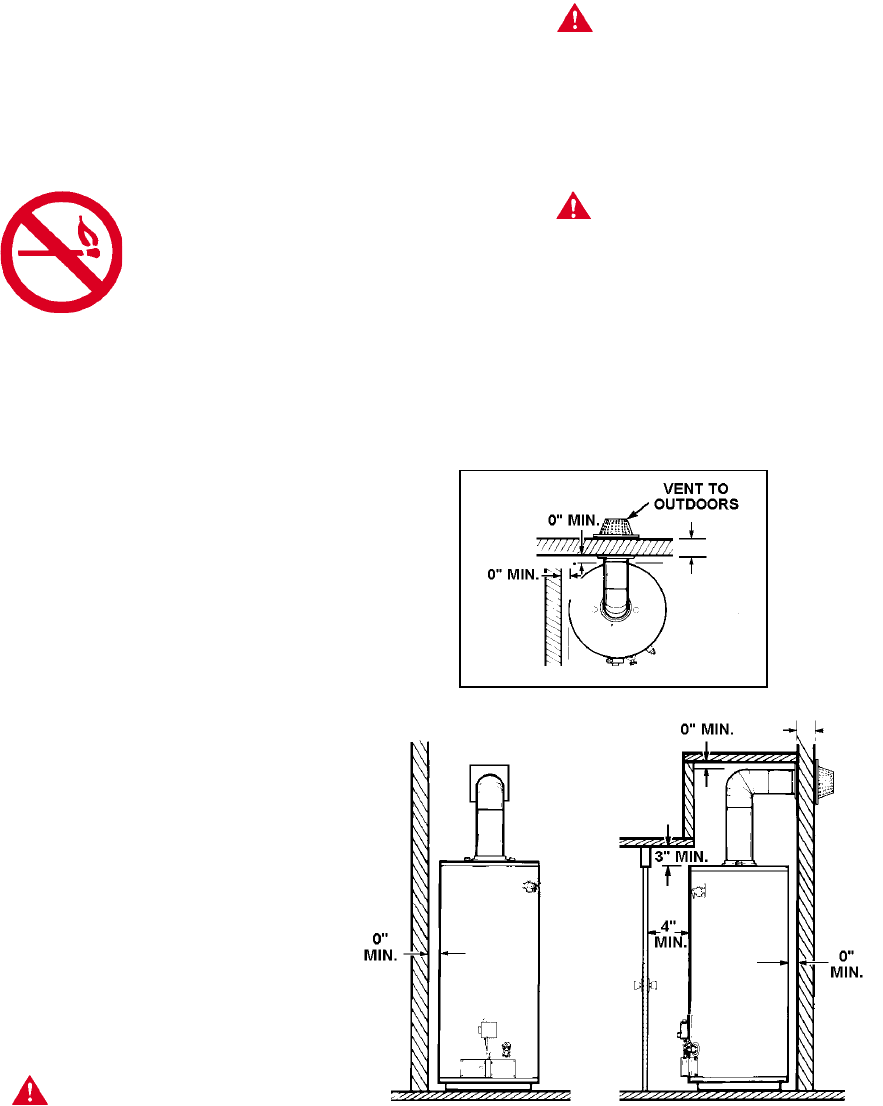
WARNING
MINIMUM CLEARANCES BETWEEN THE WATER HEATER AND
COMBUSTIBLE AND NONCOMBUSTIBLE CONSTRUCTION
ARE: 0 INCHES FROM SIDES, 0 INCHES FROM BACK, 4 INCHES
FROM FRONT OF JACKET TO CLOSET DOOR AND 3 INCHES
FROM TOP OF JACKET TO COMBUSTIBLE AND
NONCOMBUSTIBLE MATERIAL. MINIMUM VENT CLEARANCE: 0
INCHES. PROVIDE 24 INCHES FRONT CLEARANCE FOR
SERVICING AND ADEQUATE CLEARANCE BETWEEN THE
JACKET TOP & CEILING FOR SERVICING THE FLUE AREA.
(SEE FIGURE 3).
FIGURE 3
COMBUSTION AIR AND VENTILATION
When determining the installation location for a direct vent water
heater, snow accumulation and drifting should be considered in
areas where applicable.