


14
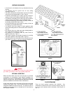
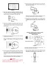
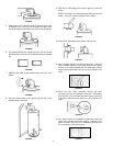
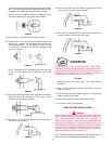
FIGURE 57
5. Making sure the 6” diameter elbow is centered around the
3” diameter flue, secure the 6” diameter vent pipe using
four sheet metal screws at the connection of the jacket top.
FIGURE 58
6. The standard kit includes a single piece of 3” flue and 6” vent
pipe which will not be used in conjunction with the horizontal
kit.
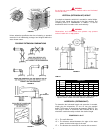
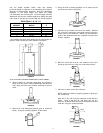
FIGURE 59
7. Slide the vent collar (to be installed later) over the 6” vent
elbow.
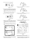
FIGURE 60
8. Place the water heater at the opening in the wall, at the
predetermined clearance.
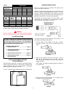
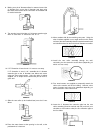
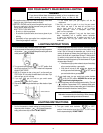
FIGURE 61
9. Slide the 6” telescoping vent section apart to reveal the
beads.
NOTE: The section of 6” pipe with beads will connect to the
elbow. Using the caulking supplied, fill the beads.
FIGURE 62
10. Insert the 6” telescoping vent section into the wall.
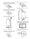
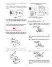
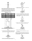
FIGURE 63
11. Move outdoors with all the remaining vent parts. Using the
tube of sealant supplied, run an ample amount on the inside
surface of the collar assembly that will contact the exterior
wall and also fill the bead on the end of the 6” diameter vent
collar.
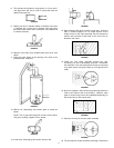
FIGURE 64
12. Install the vent collar assembly through the wall,
connecting it to the 6” telescoping extension. Remember,
the extension is not connected yet and it may be necessary
to go back indoors and push it back up for a tight fit to the
collar.
FIGURE 65
13. Four wood screws are supplied to temporarily attach the
collar to the exterior wall to the building. However, other
types of screws may have to be substituted depending on
the construction of the exterior wall.
FIGURE 66