


5
Installation
REQUIRED ABILITY
INSTALLATION OR SERVICE OF THIS WATER HEATER
REQUIRES ABILITY EQUIVALENT TO THAT OF A LICENSED
TRADESMAN IN THE FIELD INVOLVED. PLUMBING AND
ELECTRICAL WORK ARE INVOLVED.
GENERAL
The installation must conform to these instructions and the local
code authority having jurisdiction. Grounding and electrical wiring
connected to the water heater must also conform to the current
version of the
National Electrical Code NFPA-70 or for Canadian
requirements the current version of the
Canadian Electric Code,
CAN/CSA-C22.2 No. M91. These codes may be obtained from
the following institutes; The NFPA-70 is available from the National
Fire Protection Association, 1 Batterymarch Park, Quincy, MA
02269. The CAN/CSA C22.2 No. M91 is available from the
Canadian Standards Association, 178 Rexdale Blvd., Toronto
Ontario, Canada M9W 1R3.
If your location requires the installation of the water heater to
comply with National Sanitation Foundation requirements, the
heater must be sealed to the floor so as to prevent seepage
underneath the heater. The following are recommended sealants
that may be used on all types of flooring except concrete GE
Silicone Seal RTV-120, 103, 108, and 109.
LOCATION
For proper installation, the heater should be installed on a level
surface.
LOCATE THE WATER HEATER NEAR A FLOOR DRAIN. THE
HEATER SHOULD BE LOCATED IN AN AREA WHERE
LEAKAGE FROM THE HEATER OR CONNECTIONS WILL NOT
RESULT IN DAMAGE TO THE ADJACENT AREA OR TO LOWER
FLOORS OF THE STRUCTURE.
WHEN SUCH LOCATIONS CANNOT BE AVOIDED, A SUITABLE
DRAIN PAN SHOULD BE INSTALLED UNDER THE HEATER.
Such pans should be fabricated with sides at least 2" deep, with
length and width at least 2" greater than the diameter of the heater
and must be piped to an adequate drain. Drain pans suitable for
these heaters are available from your distributor or Product Service
Division, A.O. Smith Water Heater Parts Fulfillment, 125 Southeast
Parkway, Franklin, TN 37068.
Water heater life depends upon water quality, water pressure and
the environment in which the water heater is installed. Water
heaters are sometimes installed in locations where leakage may
result in property damage, even with the use of a drain pan piped
to a drain. However, unanticipated damage can be reduced or
prevented by a leak detector or water shut-off device used in
conjunction with a piped drain pan. These devices are available
from some plumbing supply wholesalers and retailers, and detect
and react to leakage in various ways:
• Sensors mounted in the drain pan that trigger an alarm or turn
off the incoming water to the water heater when leakage is
detected.
• Sensors mounted in the drain pan that turn off the water supply
to the entire home when water is detected in the drain pan.
• Water supply shut-off devices that activate based on the water
pressure differential between the cold water and hot water pipes
connected to the water heater.
• Devices that will turn off the gas supply to a gas water heater
while at the same time shutting off its water supply.
Locate the heater close to the point of major hot water usage and
the power supply.
• Try to make hot water piping and branch circuit wiring as short
as possible.
• Insulate hot and cold water piping where heat loss and
condensation may be a problem.
THE HEATER SHOULD NOT BE LOCATED IN AN AREA WHERE
IT WILL BE SUBJECT TO FREEZING.
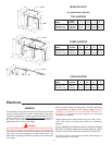
Suggested clearances from adjacent surfaces are 18 inches in
front for access to the controls and elements and 12 inches from
top. The heater may be installed on or against combustible
surfaces.
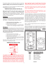
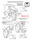
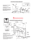
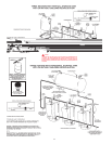
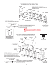
WATER LINE CONNECTIONS
This manual provides detailed installation diagrams (see back
section of this manual) for typical methods of application for the
water heaters. The water heater may be installed by itself, or with
a separate storage tank, on both single and two-temperature
systems. When used with a separate storage tank, the circulation
may be either by gravity or by means of a circulating pump. When
a circulating pump is used it is important to note that the flow rate
should be slow so that there will be a minimum of turbulence
inside the heater.
CAUTION
A closed system will exist if a check valve, pressure reducing
valve, or a water meter is installed in the cold water line between
the water heater and street main (or well).
Excessive pressure may develop causing premature tank failure
or intermittent relief valve operation. This type of failure is not
covered by the limited warranty. An expansion tank may be
required in the inlet supply line between the appliance and the
meter or valve to compensate for the thermal expansion of water.
If a water heater is installed in a closed water system, contact the
water supplier or local plumbing inspector on how to control this
situation.
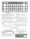
RELIEF DEVICES
CAUTION
TO REDUCE THE RISK OF EXCESSIVE PRESSURES AND
TEMPERATURE IN THIS WATER HEATER, INSTALL
TEMPERATURE AND PRESSURE PROTECTIVE EQUIPMENT
REQUIRED BY LOCAL CODES but not less than a combination
temperature and pressure relief valve certified by a nationally
recognized testing laboratory that maintains periodic inspection
of production of listed equipment or materials, as meeting the
requirements for Relief Valves for Hot Water Supply Systems,
ANSI Z21.22 /CSA 4.4 (current version).
This valve must be marked with a maximum set pressure not to
exceed the marked maximum working pressure of the water heater.
INSTALL THE VALVE INTO AN OPENING PROVIDED AND
MARKED FOR THIS PURPOSE IN THE WATER HEATER, AND
ORIENT IT OR PROVIDE TUBING SO THAT ANY DISCHARGE
FROM THE VALVE WILL EXIST ONLY WITHIN 6 INCHES ABOVE,
OR AT ANY DISTANCE BELOW THE STRUCTURAL FLOOR AND
CANNOT CONTACT ANY LIVE ELECTRICAL PART. THIS
DISCHARGE OPENING MUST NOT BE BLOCKED OR REDUCED
IN SIZE UNDER ANY CIRCUMSTANCES.