


16
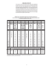
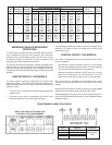
Full Load Current in Amperes
KW Number of Element Single Phase Three Phase No. of No. of
Input Elements Wattage 208V 240V 277V 480V 208V 240V 480V Thermostats Fuses
6 2000 28.8 25.0 21.7 12.5 16.7 14.4 7.2
9 3000 43.3 37.5 32.5 18.8 25.0 21.7 10.8
12 3 4000 57.7 50.0 43.3 25.0 33.3 28.9 14.4 3 6
13.5 4500 64.9 56.3 48.7 28.1 37.5 32.5 16.2
15 5000 72.1 62.5 54.2 31.3 41.6 36.1 18.0
18 6000 - - - 75.0 65.0 37.5 - - - 43.3 21.7
18 3000 86.5 - - - - - - - - - 50.0 - - - - - -
24 4000 115.4 100.0 86.6 50.0 66.6 57.7 18.9
27 6 4500 129.8 112.5 97.5 56.3 74.9 65.0 32.5 6 12
30 5000 144.2 125.0 108.3 62.5 83.3 72.2 36.1
36 6000 - - - 150.0 130.0 75.0 - - - 86.6 43.3
36 4000 173.1 - - - - - - - - - 99.9 - - - - - -
40.5 9 4500 194.7 168.8 146.2 84.4 112.4 108.3 54.1 9 18*
45 5000 216.3 187.5 162.5 93.8 124.9 108.3 54.1
54 6000 - - - 225.0 194.9 112.5 149.9 129.9 65.0
AMPERAGE TABLE/OVERCURRENT
PROTECTION
The table above provides the total connected heating element
load in amperes for branch circuit conductor and overcurrent
protection sizing. Single-phase heaters are two wire circuits.
Three-phase heaters are three wire circuits. In addition to the
foregoing, a grounded conductor is required.
The rating of the overcurrent protection must be computed on the
basis of 125% of the total connected load amperage. Where the
standard ratings and settings do not correspond with this
computation, the next higher standard rating or setting should be
selected.
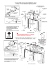
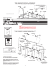
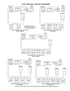
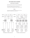
HEATER CIRCUITS - DVE MODELS
The water heater's electrical components are pictured and
identified on page 2. The model and rating plate illustration on
page 4 identifies heater circuit ratings. The DVE model has two
electrical circuits.
• The control circuit, where the thermostat directly operates the
contactor coils.
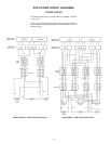
• The power circuit, which is operated by the control circuit
carries the electrical load of the heating elements.
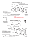
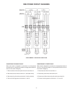
The following describes the heater circuits and includes wiring
diagrams. All heater circuits are designed for 50/60 cycle
alternating current.
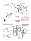
CONTROL CIRCUIT - DVE MODELS
The heater is equipped with one of the following 120V control
circuits, resulting in:
• Simultaneous element operation where all of the heating
elements are operated by one thermostat. This is the standard
circuit and may be used with up to nine elements.
• Sequenced element operation where each row of three
elements are operated by its own thermostat. This is an
optional circuit and may be used with six or nine elements.
The control circuit is operated on single-phase 120V current
obtained from the control transformer or as shown in the wiring
diagram.
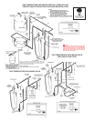
Beginning at the fuse block, control circuit wiring is 14 Awg, AWM
(Appliance wiring material) type, rated 600 volts, 105°C.
Standard equipment includes control circuit fusing using two, 3
amp, class G fuses with 600 volt rating. Do not substitute fuses of
a different rating.
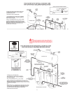
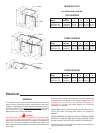
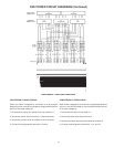
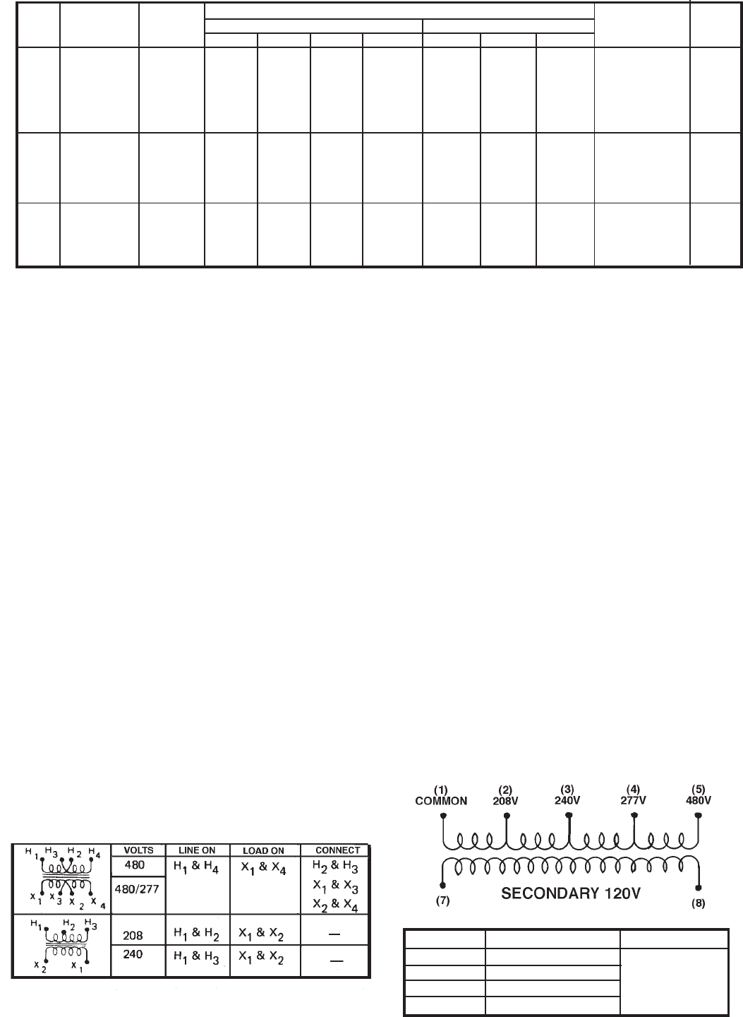
TRANSFORMER CONNECTION TABLES
VOLTS LINE ON LOAD ON
208 COMMON & 208
240 COMMON & 240 SECONDARY
277 COMMON & 277 120V
480 COMMON & 480
NOTE: THIS TABLE TO BE USED FOR
8 TAP AND 5 TAP TRANSFORMERS