


15
BRANCH CIRCUIT
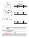
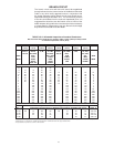
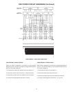
The branch circuit wire and fuse size should be established
through reference to the current version of the National Electrical
Code or any other locally approved source in conjunction with
the heater amperage rating. Branch circuit wires should have a
temperature rating no less than 75°C. For convenience, portions
of the wire size tables from the code are reproduced here. It is
suggested the electrician size the branch circuit at 125% of the
heater ampere rating and further increase wire size as necessary
to compensate for voltage drop in long runs. Branch circuit voltage
drop should not exceed 3% at the heater.
TABLE 310-16. Allowable Ampacities of Insulated Conductors
Not more than three conductors in raceway, cable, or earth (directly buried), based
on ambient temperature of 30°C (86°F)
Size Temperature Rating of Conductor, See Table 310-13 Size
60°C 75°C 85°C 90°C 60°C 75°C 85°C 90°C
(140°F) (167°F) (185°F) (194°F) (140°F) (167°F) (185°F) (194°F)
TYPES TYPES TYPES TYPES TYPES TYPES TYPES TYPES
RUW, T FEPW, V, MI, TA, TBS, RUW, T RH, RHW, V, MI, TA, TBS,
TW, UF RH, RHW, SA, AVB, TW, UF RUH, SA, AVB,
AWG RUH, SIS, +FEP, THW, SIS, AWG
THW +FEPB, THWN, +RHH,
MCM THWN, +RHH, XHHW, +THHN, MCM
XHHW, +THHN, USE +XHHW*
USE, ZW +XHHW*
COPPER ALUMINUM OR COPPER-CLAD ALUMINUM
18 . . . . . . . . . . . . 21 . . . . . . . . . . . . . . . . . . . .
16 . . . . . . . . 22 22 . . . . . . . . . . . . . . . . . . . .
14 15 15 25 25 . . . . . . . . . . . . . . . . . . . .
12 20 20 30 30 15 15 25 25 12
10 30 30 40 40 25 25 30 30 10
84045 50503040 40 408
65565 70704050 55 556
47085 90905565 70 704
3 80 100 105 105 65 75 80 80 3
2 115 120 120 75 90 95 95 2
1 130 140 140 100 110 110 1
0 150 155 155 120 125 125 0
00 175 185 185 135 145 145 00
000 200 210 210 1155 165 165 000
0000 230 235 285 180 185 185 0000
250 255 270 270 205 215 215 250
300 285 300 300 230 240 240 300
350 310 325 325 250 260 260 350
400 335 360 360 270 290 290 400
500 380 405 405 310 330 330 500
CORRECTION FACTORS
Ambient For ambient temperatures over 30°C, multiply the ampacities shown above by the Ambient
Temp. °C appropriate correction factor to determine the maximum allowable load current. Temp. °F
31-40 .82 .88 .90 .91 .82 .88 .90 .91 86-104
41-50 .58 .75 .80 .82 .58 .75 .80 .82 105-122
51-60 . . . . .58 .67 .71 . . . . .58 .67 .71 123-141
61-70 . . . . .35 .52 .58 . . . . .35 .52 .58 142-158
71-80 . . . . . . . . .30 .41 . . . . . . . . .30 .41 159-176
+The load current rating and the overcurrent protection for these conductors shall not exceed 15 amperes for 14 AWG, 20 amperes for 12 AWG, and 30 amperes for
10 AWG copper; or 15 amperes for 12 AWG and 25 amperes for 10 AWG aluminum and copper-clad aluminum.
*For dry locations only. See 75°C column for wet locations.