


16
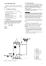
2.1.6 Electrical connection
All electrical connections must be carried out by a
registered electrical contractor to the relevant
regulations.
The BFM must be connected to a supply voltage by
means of a permanent electric connection and have a
feeder cable not less than 3 x 1,0 mm².
Supply voltage Supply network Mínimum fuse
frequency required
220/240 VAC 50 Hz 1 A
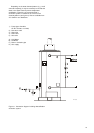
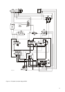
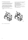
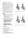
The electrical diagram of the BFM-heater and the
connections in the control-column are shown in figures
12 and 13.
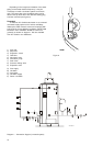
Electrical connection diagram BFM
(see figure 12)
A) Jacket
B) Transformer 230V/238V/2VA
C) Air proving switch
D) EMC single phase filter
E) RESET knob
F) Thermostat frost
G) Thermostat regulation
H) Switch ON/OFF
K) Thermostat overheat 93°C
L) Thermostat high limit 84°C
M) Automatic burner controller
N) Plastic connector strip
P) Earth terminal block
S) Relais
Colour-code cables:
1 Blue
2 Brown
3 Yellow/green
4 Red
5 White
6 White/orange
7 White/violet
8 Black
9 Black/green
10 Black/red
11 Black/white