


14
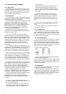
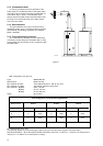
Flue configuration / horizonal discharge BFM-unit
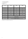
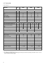
Measurement BFM 30 BFM 50 BFM 80
min. max. min. max. min. max.
A 0 7000 0 7000 0 7000
B 0 7000 0 7000 0 7000
A+B < 7000 < 7000 < 7000
All measurements are in mm.
The following applies for the horizontal pipe: slope of at least 5 mm per metre of pipe to the water heater.
NB. Measurements A + B are the total permissible dimensions of the flue, i.e. when A = 1 metre, B = 6 metres (total 7
metres) or A = 4 metres, B = 3 metres (total 7 metres).
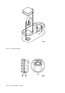
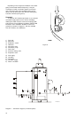
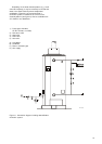
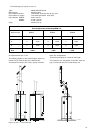
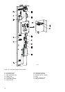
- Wall configuration (see figure 9)
Type: M2000 MDV SE
Manufacturer: Meulink & Grol
Pipe material flue tube: Thick-walled aluminium with lip ring seal.
Pipe material air supply: Thin-walled galvanised steel plate.
Pipe diameter BFM 30: Ø 80 / 125 mm
BFM 50: Ø 100 / 150 mm
BFM 80: Ø 130 / 200 mm
Angle: 90° (2 max.)
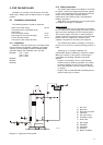
2.1.3 Condensation drain
In order to guarantee the correct operation of the
water heater, the condensate drain of the water heater
must open into the sewer interrupted, provided with an
extra stench trap or siphon. A condensation drain
section fixed to the water heater should be fitted under
the slope. The condensate drain of the water heater
must never be sealed.
2.1.4 Gas connection
The gas installation may only be carried out by a
registered installer and in accordance with the relevant
local authority and building regulations and followint
British standards.
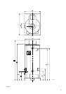
2.1.5 Flue connections (concentric)
The combined flue discharge and air intake tubes
(concentric) should always be assembled with a rising
slope towards the flue terminal, and in accordance with
the table below.
figure 9
IMD-0060