


11
IMD-0065
2. FOR THE INSTALLER
If possible, use a trolley or fork-lift truck to move the
water heater. Always move the water heater in an upright
position.
2.1 Installation instructions
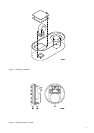
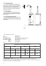
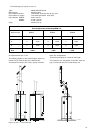
The following distances should be observed:
- Sides of the water heater: 100 cm
(free space for the accessibility of the
hand holes)
- Rear of the water heater: 15 cm
- Around top-box and concentric pipe: 15 cm
- Front of the water heater: 100 cm
(free space to take out bar burners)
2.1.1 Installation
Installation should be carried out in accordance with
all local authority and building regulations, local water
authority and fire regulations and the following British
standards: British Gas Publication UP1 and UP2.
BS 5482 part 1 1979
part 2 1979
part 3 1979
BS 6644
BS 6700
BS 6798
2.1.2 Water connections
A.O. Smith water heaters are suitable for connection
to vented, unvented and pumped pressurised systems.
In each case appropriate valves and fittings should be
used to ensure the system complies with the
requirements of the water by laws, and appropriate
building regulations.
When fitting it is essential the rules of 'good practice'
are applied at all stages of installation.
Vented systems
If the water heater is to be connected to a cold feed
tank or cistern the hot water supply pipe must include an
open vent which discharges over the cold feed cistern.
The cold feed cistern must have an actual capacity of
greater volume than the hourly recovery rate of the water
heater(s) which it supplies.The minimum actual
capacity is 50 gallons or 227 litres. See diagram 5.
A.O. Smith water heaters are tested to a maximum
pressure of 12 bar and a maximum working pressure of
8 bar.
Dead legs on a hot water installation are
undesireable. Where possible they should be avoided.
Where the inclusion on the system of a dead leg is
unavoidable the following restrictions should be
applied:
- for pipes not exceeding 19 mm. inside diameter;
maximum lengh of dead leg permitted 12.0 metres;
- for pipes exceeding 19 mm. but not exceeding 25
mm. inside diameter; maximum length of dead leg
7.5 metres;
- for pipes with an inside diameter exceeding 25 mm.
maximum dead leg 3.0 metres.
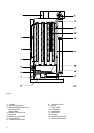
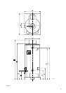
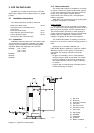
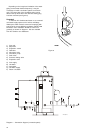
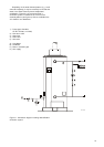
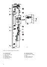
1) Gas cock
2) Stop valve
3) Three way vent valve
4) T&P valve
5) Non-return valve
6) Circulation pump
7) Drain valve
A) Gas supply
B) Hot Water
C) Cold Water
D) Overflow
E) Return circulation
Diagram 5 - Typical UK vented system