


20
OPERATION
SEQUENCE OF OPERATION
Typical Control/Appliance Operating Sequence
1. When the control is powered, it should display the unit model,
water temperature, setting temperature and heater status.
2. If the control determines that the actual water temperature inside
the tank is below the programmed temperature setpoint less the
differential, a call for heat is activated.
3. The control then performs selected system diagnostic checks.
This includes conrming the proper state of the air/gas switches
and ECO limit device.
4. If all checks are successfully passed, the combustion blower is
energized for the pre-purge cycle.
5. When the pre-purge cycle is complete, power is applied to the
ignitor element for the ignitor warm-up period.
6. At the conclusion of the igniter warm-up period, the gas valve
will open, allowing gas to enter the burner chamber.
7. The igniter will remain on for a short predetermined time period,
then will be turned off.
8. The control will monitor the ame sense probe to conrm a
ame is present. If a ame is not veried within predetermined
time period, the gas valve will immediately be closed, and
the blower will continue to run for approximately 30 seconds
interpurge. The control will try for ignition two more times
before lockout.
9. If a ame is conrmed, the control will enter the heating mode
where it will continue heating the tank water until the setpoint
temperature plus differential is reached. At this point, the gas
valve is closed and the control enters the post-purge cycle.
10. The combustion blower will run for the duration of the post purge
cycle to purge the system of all combustion gases. When the
post purge cycle is complete, the blower is de-energized and
will coast to a stop.
11. The control will now enter the idle state while continuing to
monitor the internal tank water temperature and the state of other
system devices. If the temperature drops below the setpoint
value less differential, the control will automatically return to
step 2 and repeat the entire operating cycle.
ELECTRONIC CONTROL
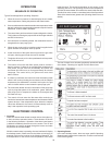
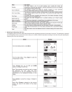
1. Overview
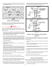
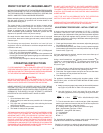
Interaction with the water heater controller is done through an up,
a down and three operation buttons. These buttons are shown
in the following illustration. Operation of the three lower buttons
is dened immediately above them on the screen. The UP and
DN buttons are used to navigate through the menus and make
adjustments to the water heater.
While the water heater is operating, the user interface will display
the desktop screen (if there are no active faults or warnings). An
example of this screen is shown in the following illustration. The
rst temperature on this screen is the temperature of the water
inside the tank. The second temperature on this screen is the
Operating Set Point. The Operating Set Point is the temperature
at which the water heater will maintain the water inside the tank.
The third line on the screen is a text description of the Operational
State of the water heater (please see Operating States for more
details).
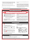
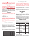
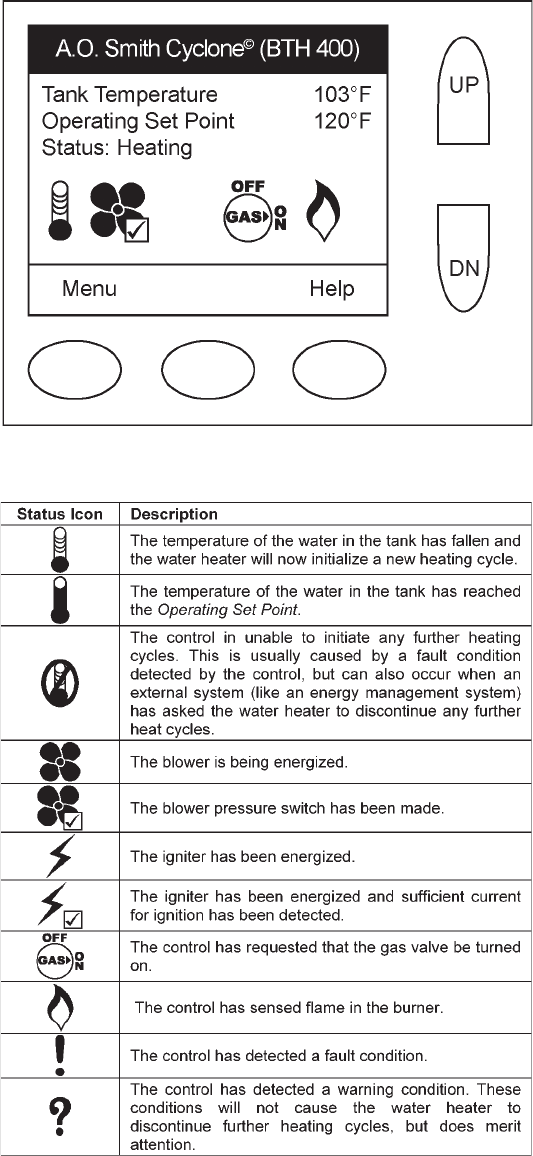
The row of status icons describe graphically operational details
of the heater. Following is a legend of all the status icons:
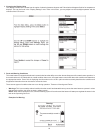
2. Operating States
In the main desktop screen, there are some specic Operating
States that are indicated on the status line. These are summerized
in the following table: