25
VENTING
Vent sizing, installation and termination should be in accordance
with this installation manual. This boiler must be vented using
PVC/CPVC or Stainless Steel materials.
All electrical power and gas must be turned off prior to any
installation of the venting system.
VENT INSTALLATION CONSIDERATIONS
This boiler is a category IV appliance that can be vented using
room air for intake combustion air, or direct vented so that all
intake air for combustion comes from the outside through a
sealed pipe. When installing this appliance as direct vent, special
vent kits are required.
In cold climates any water vapor remaining in the ue gases will
condense into a cloud of vapor at the point where the vent system
exits the building. Special consideration is recommended, before
locating the vent termination near walkways, windows and
building entrances.
Direct venting into dead spaces such as alleys, atriums, and
inside corners can cause recirculation of ue gases. Recirculation
of ue gases will cause sooting, premature failure of the heat
exchanger, and icing of the combustion air intake during severe
cold weather. To prevent the recirculation of ue gases, maintain
as much distance as possible between the combustion air
intake and the exhaust vent terminal. Due to large volumes of
ue gases, multiple boiler applications also require additional
distance between the intake and the exhaust terminals.
This boiler can be vented with PVC/CPVC or an UL approved AL
29-4C Stainless Steel venting material which are explained in the
following pages.
PVC/CPVC INSTALLATION:
Installation must comply with local requirements and with the
National Fuel Gas Code, ANSI Z223.1 for U.S. installations or
CSA B149.1 for Canadian installations.
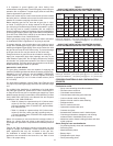
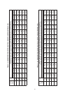
Refer to Table 13 on Page 36 for PVC/CPVC piping materials.
All PVC vent pipes must be glued, properly supported, and
the exhaust must be pitched a minimum of a 1/4 inch per foot
back to the boiler (to allow drainage of condensate).
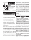
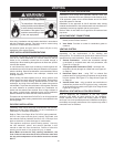
This appliance requires a special venting system. Use only
the vent materials, primer, and cement specified in this
manual to make the vent connections. Failure to follow this
warning could result in fire, personal injury, or death.
Note: Make sure that for PVC venting installation, the
first 10 feet of vent must be CPVC or stainless steel and
the set point temperature of the boiler must not exceed
200 °F.
STAINLESS STEEL INSTALLATION:
Installations must comply with applicable national, state, and
local codes. Stainless steel vent systems must be listed as a UL-
1738 approved system for the United States and a ULC-S636
approved system for Canada.
Installation of the approved AL 29-4C stainless steel venting
material should adhere to the stainless steel vent manufacturer’s
installation instructions supplied with the vent system.
Refer to Table 14 and Table 15 on Page 36 for air intake and vent
pipe sizes.
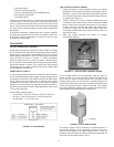
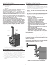
AIR INTAKE/VENT CONNECTIONS
1. Air Intake Adapter: Provides an inlet for combustion air
directly to the unit from outdoors.
2. Vent Outlet: Provides an outlet for combustion gases to
outdoors.
VENTING SYSTEM
This boiler may be installed in six separate orientations
depending on the require ments of the building and
the appliance. The installer must decide which method is most
appro priate for each installation. These orientations are:
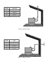
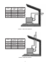
1. Vertical Termination - vertical vent termi na tion through
un-enclosed or en closed areas with roof penetration, see
Figure 25 on Page 28.
2. Through-the-Wall Termination (TWT) - hori zontal vent
termination directly through an outside wall, see Figure 26
on Page 28.
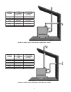
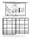
3. Horizontal Direct Vent - using TWT to exhaust ue
prod ucts and PVC piping to bring combus tion air to the boiler
from the outside. See Figure 27 on Page 29 and Figure 30
on Page 30.
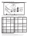
4. Vertical Direct Vent - using a vertical vent termination to
exhaust ue products and PVC piping to bring combustion
air to the boiler from outside, see Figure 28 on Page 29 and
Figure 29 on Page 30.
GENERAL VENT INSTALLATION PROCEDURE
Prior to beginning the installation of the vent system,
deter mine and obtain all parts re quired for the installa tion.
Proper operation of the boiler and vent ing system is depen-
dent upon use of all speci ed parts and installa tion tech niques;
both safety and proper perfor mance of the system may suffer if
in structions are not followed.


