


45
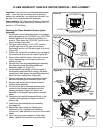
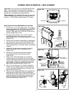
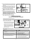
Removing Old Burner :
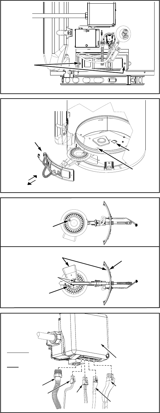
11. After noting the position of the condensation drain
hole on the top of the burner. Turn the inner door/
manifold/burner assembly upside. Using a phillips
head screwdriver remove the 2 screws attaching
the burner to the manifold pipe (saving screws for
reinstallation later) (Figure 99).
Installing New Burner :
12. Care MUST be taken to ensure the burner is
installed correctly on the inner door/manifold
assembly. Position the new burner upside down
with the orientation of the burner’s condensation
drain as shown in illustration (Figure 99).
13. Align the screw holes on the inner door/manifold
assembly. Using the two screws removed in step
11, installed the new burner to the inner door/
manifold assembly (rotate the assembly to visually
check the top portion of the burner assembly and
confirm the orientation of the condensation drain
hole on the top of the burner is toward the back as
shown in the illustration) (Figure 99).
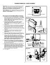
Installation Caution Must Be Taken:
14. Prior to installing the new inner door/manifold/
burner assembly, look inside the burner chamber
to fully understand the correct positioning of the
burner assembly and burner manifold tab. It may
be necessary to use a flashlight to ensure correct
placement. Care must be taken so as to not
damage any electrical wiring, components or the
air pressure tubing as you are installing the new
inner door/manifold/burner assembly.
Extra caution should be taken to ensure
that electrical wiring, air hose, fiberglass
insulation nor any other object is between
door gasket and combustion chamber shield.
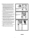
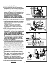
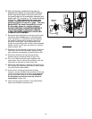
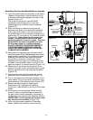
Reinstalling The Inner Door/Manifold/Burner Assembly
15. Insert the manifold/burner assembly in the burner
chamber compartment, making sure that the tip
of burner manifold tab engages in the slot of the
bracket (Figure 98).
The tip end of the burner manifold MUST
be placed in the slotted portion under the
condensation pan to obtain proper installation
(Figure 98).
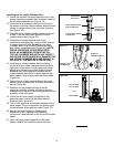
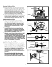
Figure 97.
1/4” HEX
HEAD SCREW
Figure 98.
INNER DOOR/
MANIFOLD/BURNER
ASSEMBLY
SLOT
BURNER’S
TIP END
TAB
INSTALL
REMOVE
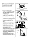
Figure 99.
BURNER’S
CONDENSATION DRAIN
TWO SCREWS
TOP VIEW
BOTTOM VIEW
ORIENTATION OF SCOOP
TO BE ON THE SAME SIDE
AS THE VIEW PORT
VIEW PORT
BURNER’S
CONDENSATION DRAIN
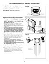
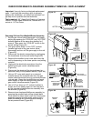
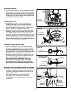
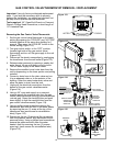
IMPORTANT:
WHEN BRUSHING ON AN
APPROVED NONCORROSIVE
LEAK DETECTION SOLUTION,
DO NOT SPLASH SOLUTION
ONTO ELECTRICAL CON-
NECTIONS.
IGNITER/
FLAME
SENSE
CONNECTOR
MANIFOLD TUBE
POWER SUPPLY
TRANSFORMER
CONNECTOR
PRESSURE
SWITCH/FAN,
FV SENSOR
CONNECTOR
DISPLAY, ANODE
ROD CONNECTOR
GAS CONTROL
VALVE/THERMOSTAT
Figure 100.