


33
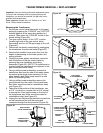
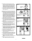
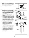
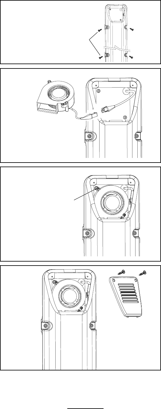
Figure 53.
SECURE WITH
SCREWS REMOVED
EARLIER
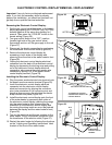
25. Install the air intake chamber box by rotating
the top of the air intake chamber box from left to
right (only a few inches in both directions) while
pressing on the bottom portion of the air intake
chamber box. When properly installed the air
intake chamber box will be in place against the
water heater’s side aligning with the screw holes.
26. Secure the air intake chamber box to the water
heater’s side by reusing the 4 screws removed in
step 13 (Figure 53).
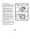
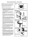
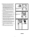
Installing the Fan in the Air Intake Chamber Box:
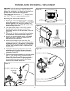
27. Plug the electrical connections of the fan into the
wiring harness: Align the electrical connections in
such a position as to ensure the locking portions
of the connections are on the same side. Gently
push the electrical connectors together until the
snap lock on the wiring harness engages the
angular lock on the fan connector. Do Not use
undue force in pushing these connectors together
(Figure 54). (Note: Connectors are designed in
such a manner if the connection is not properly
aligned they will not lock together).
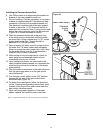
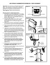
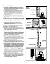
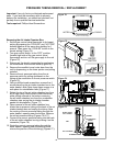
28. Replace the fan inside the air intake chamber
box. It is imperative that the square portion of the
fan air outlet be placed inside the raised square
portion of the air intake chamber fan compartment
(Figure 55).
29. Ensuring the fan is properly aligned in the air
intake chamber, secure the fan in place using the
2 screws removed in step 9 (Figure 55).
30. Route the wiring inside the fan box to the outer
edge of the fan in such a manner to ensure it will
not be pinched or damaged upon installation of
the air intake screen (Figure 55).
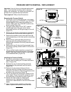
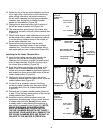
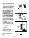
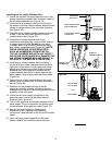
31. Install the air intake chamber screen, ensuring that
the prongs of the lower portion of the air intake
chamber screen are in place in the holding slots.
Using the 2 screws removed in step 6, secure the
air intake chamber screen (Figure 56).
32. Reattach the 3-wire wiring harness connector to
the gas control valve (Figure 47).
33. Check the air hose tubing connection to the
pressure switch to ensure the tubing has not
loosen up or pulled off.
34. Turn on the electrical and the gas supplies to the
water heater. Plug in the electric connection from
the transformer to the electric outlet (Figure 46).
35. Restart the water heater by following the
directions on the “Lighting and Operating
Instructions” label located on the front of the water
heater.
36. Upon verifying proper operation of the water
heater, replace the manifold cover/outer door.
Figure 54.
GENTLY PUSH THE ELECTRICAL
CONNECTORS TOGETHER UNTIL
IT IS SNAP LOCKED.
FAN
Figure 55.
INSTALL THE FAN USING THE
TWO SCREWS REMOVED
EARLIER.
FAN
Figure 56.
INSTALL THE AIR INTAKE
CHAMBER SCREEN.