


36
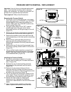
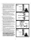
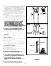
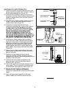
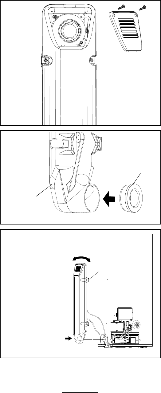
25. Install the air intake chamber screen, ensuring that
the prongs of the lower portion of the air intake
chamber screen are in place in the holding slots.
Using the 2 screws removed in step 8, secure the
air intake chamber screen (Figure 65).
26. Check the air pressure tubing to the fitting on the
of the air intake chamber box and route tubing
in molded inlaid of the air intake chamber box
(Figure 63).
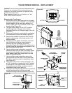
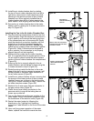
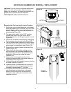
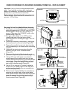
27. Reinstall the air intake chamber gasket (removed
in step 12) on the back lower portion of the new air
intake chamber box (Figure 66).
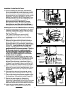
28. Install the new air intake chamber box to the
combustion chamber pipe. Using a small amount
of soapy water will help. Do not get any water
or soapy water on any electrical connections
or gas control components (Figure 67). NOTE:
UNDUE PRESSURE OR SUDDEN FORCE
SUCH AS HAMMERING OR BEATING ON
THE AIR CHAMBER BOX WITH ANY OBJECT
INCLUDING YOUR HANDS WILL DAMAGE THE
AIR INTAKE CHAMBER BOX AND RESULT IN
FAILURE TO THE HEATER’S OPERATION.
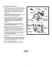
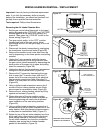
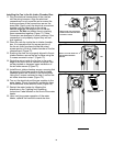
29. Install the air intake chamber box by rotating
the top of the air intake chamber box from left to
right (only a few inches in both directions) while
pressing on the bottom portion of the air intake
chamber box. When properly installed the air
intake chamber box will be in place against the
water heater’s side aligning with the screw holes
(Figure 67).
30. Secure the air intake chamber box to the water
heater’s side by reusing the 4 screws removed in
step 11 (Figure 67).
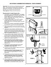
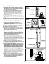
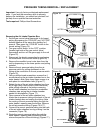
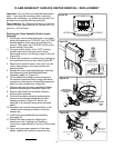
31. Plug in the electrical flag terminals into the air
pressure switch (Figure 60).
32. Reinstall the FV sensor removed in step 7, by
depressing the snap lock to open the FV sensor
cover, route wiring through sensor cover, plug the
electrical flag terminals connections to the FV
sensor and slide the FV sensor back inside and
close the cover (Figure 60).
33. Connect the air pressure tubing to the pressure
switch (Figure 60).
34. Attach the 3-wire wiring harness connector to the
gas control valve (Figure 59).
35. Check the air hose tubing connection to the
pressure switch to ensure the tubing has not
loosened up or pulled off (Figure 60).
36. Turn on the electrical and the gas supplies to the
water heater. Plug in the electric connection from
the transformer to the electric outlet (Figure 58).
37. Restart the water heater by following the
directions on the “Lighting and Operating
Instructions” label located on the front of the water
heater.
38. Upon verifying proper operation of the water
heater, replace the manifold cover/outer door.
Figure 66.
AIR INTAKE
CHAMBER BOX
REINSTALL
CHAMBER GASKET
Figure 65.
INSTALL THE AIR INTAKE
CHAMBER SCREEN.
Figure 67.
ROTATE FROM
LEFT TO RIGHT
AND
PUSH INWARD
INSTALL SCREWS