


8
3.3
P
OWER
S
WITCH
/
R
ESET
S
WITCH
/
H
ARD
D
ISK
D
RIVE
LED
C
ONNECTORS
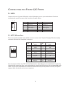
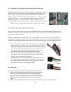
Connected to your front panel are LED and switch leads for power, reset, and
HDD LED activity. Attach these to the corresponding connectors on your
motherboard. Consult your motherboard user’s manual for specific pin
header locations. For LEDs, colored wires are positive ( + ). White or black
wires are negative ( – ). If the LED does not light up when the system is
powered on, try reversing the connection. For more information on
connecting LEDs to your motherboard, see your motherboard user’s manual.
Note: Polarity (positive and negative) does not matter for switches.
3.4
R
EWIRING
M
OTHERBOARD
H
EADER
C
ONNECTIONS
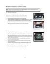
There may come a time when you need to reconfigure the pin-out of a motherboard header connector.
Examples could be for your USB header, audio input header, or some other front panel connector such
as the Power Button connector.
Before performing any work, please refer to your motherboard user’s manual or your motherboard
manufacturer's website to be sure of the pin-out needed for your connector. We strongly recommend
making a notated drawing before beginning work so that you can recover if your work gets disturbed.
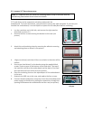
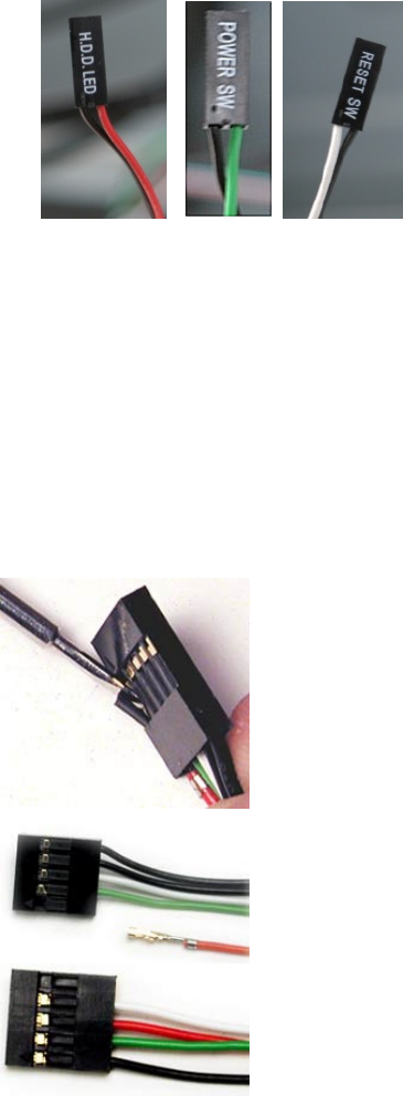
1. Determine which wires you need to remove in order to rewire your
plug to match the USB pin-outs on your motherboard (refer to your
motherboard user’s manual). Working on one connector at a time,
use a very small flathead screwdriver or similar tool to lift up on
the black tab located beside the gold posts (squares). This will
allow you to easily slide out the pins from the USB plug.
2. Working carefully so as not to damage the wires, connectors, or
pins, slowly remove the pin from the connector. Repeat these
steps for each wire you need to change.
3. Working carefully so as not to damage the wires, connectors or
pins, slowly reinsert the pin into the correct slot of the connector
then snap closed the black tab that was lifted in step 1. Repeat
these steps for each wire you need to change.
3.5
F
INAL
S
TEPS
1. Replace the right side panel, securing it with the two screws.
2. When you have replaced both side panels, attach the stand to
the case by inserting the stand into mounting holes on the
bottom of the case with the larger portion of the stand facing
forward and then sliding the stand forward until it clicks into
place.
3. Attach the power adapter to the port on the rear of the case. Your PC is now assembled.