


21
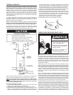
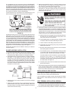
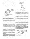
ThecondensatetrapmaybeprimedbyllingtheCONDENSATE
U-ASSEMBLY with tap water while the water heater is not operating.
The system is fully primed when the water level reaches the adaptor
connected into the Tee. In most installations the water heater will
self-primethecondensatetrapduringtherstfullheat-upcycle.If
asoundofairbubblingthroughwater(gurgling)isheardwhilethe
blowerisoperatingaftertherstheat-upcycle,thenturntheunitoff
and contact your plumber or service representative.
If these instructions are not followed, the condensate build-up will
block the exhaust outlet, which will cause improper operation.
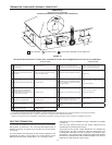
Do NOT
block or
plug any
hole in this
hex plug.
DRAIN LINE
CONDENSATE
U-ASSEMBLY,
AKA. VENT PIPE
ASSEMBLY #1
A
PPROXIMATELY
0.25" (6.35 mm)
*NO PORTION OF THE FIELD SUPPLIED DRAIN LINE BEYOND
THE 1/2" ADAPTOR MAY BE ELEVATED HIGHER THAN THE
ADAPTOR. THIS MUST BE TRUE FOR THE ENTIRE LENGTH
OF DRAIN LINE INCLUDING EXIT INTO AN APPROPRIATE DRAIN.
FIGURE 16.
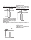
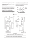
Condensate is likely to form in the venting system attached to this
water heater. The vent pipe should be sloped downward away from
theblowerassembly(notlessthan1/8”(3.2mm)norgreaterthan1/2”
(12.7mm)perfoot(30cm)maximum).Iftheventpipingisventedlevel
or sloped upwards away from the blower assembly, then adequate
means for draining and disposing of the condensate needs to be made
bytheinstaller.Two3/8”condensatehosesshouldbeconnectedto
the built in drain ports of blower outlet adaptor. If a VAA is installed,
a3/8”condensatehoseshouldbeconnectedtothebarbttingonit;
otherwisetheunusedbarbttingonventpipeassembly#2shouldbe
plugged with one of the break-away plugs. See Figure 17.
Condensate neutralizer kits are available. Contact your distributor
or Service Agency.
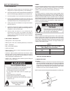
BLOWER ASSEMBLY INSTALLATION
1. This power vented water heater comes with blower assembly installed.
2. After unit is set in place, make sure blower assembly is still
mounted securely. Make sure there is no damage to blower.
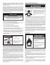
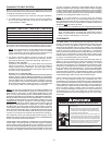
3. Condensate drains from three locations on blower assembly.
SeeFigure17.Oneexiblehoserunsfrombottomofblower
housing; two run from the ports of rubber connector at the outlet
of blower. All these three condensate hoses are connected to
barbttingsatventpipeassembly#2.Thehosefrombottom
of blower housing is clamped by two clamps and the two hoses
from rubber connector are harnessed by another clamp. Make
sure there is no kink or twist.
FIGURE 17.
4. Make sure there is no packing material in the inlet or discharge
of the blower.
5. Make sure that the plastic tubing is still attached from the air
pressure switch to the port on the blower housing. Make sure
the plastic tubing is not folded anywhere between the pressure
switch and the blower housing.
6. Make sure the ON/OFF switch is in the OFF position and that
the outer harness is connected from the blower control box to
the connector on the bottom side of the gas valve.
7. If the outer harness is not factory installed, make sure the ON/
OFF switch is in the OFF position and then connect the outer
harness from the blower control box to the connector on the
bottom side of the gas valve.
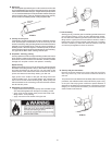
8. Do not plug in power cord until vent system is completely installed.
The Power Vent operates on 110-120 Vac. therefore a grounded
outletmustbewithinreachofthe6foot(1.8m)exiblepowercord
suppliedwiththevent(SeeFigure1).Thepowercordsupplied
may be used on a unit only where local codes permit. If local
codesdonotpermituseofexiblepowersupplycord:
A. Make sure the unit is unplugged from the wall outlet. Remove
the plastic top cap. Remove screws and open panel on the
front of the control box on the blower.
B. Cuttheexiblepowercord,leavingenoughtobeabletomake
connections.Removethestrainreliefttingfromthebox.
C. Installasuitableconduitttinginsidetheenclosure.
D. Spliceeldwiringintoexistingwiringusingcodeauthorized
method(wirenuts,etc).
E. Be certain that neutral and line connections are not reversed
when making these connections.
F. Ground heater properly. This water heater must be grounded
in accordance with the National Electrical Code NFPA 70
and/or local codes. These must be followed in all cases.
The water heater must be connected to a grounded metal,
permanent wiring system; or an equipment grounding
conductor must be run with the circuit conductors and
connected to the equipment grounding terminal or lead on
the water heater, see Figure 19.
G. Close the panel on the control box. Make sure that the access
panel is secured shut.
9. The blower discharge boot is made to accept only straight sections of
2” pipe. To start off with an elbow, a short section of the furnished
pipe, a minimum of 2 inches (5.1cm), must be cut and glued into
the end of the elbow that will mount on the discharge boot.
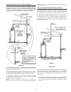
INSTALLATION OF VENT SYSTEM
Before beginning installation of piping system thoroughly read the
section of this manual VENT PIPE PREPARATION.
If you are installing your system so that it vents through roof, please
refer to section titled INSTALLATION OF VERTICAL VENT
SYSTEM.
VENT TERMINAL INSTALLATION, SIDEWALL
1. Install the vent terminal by using the cover plate as a template to
mark the hole for the vent pipe to pass through the wall. BEWARE
OF CONCEALED WIRING AND PIPING INSIDE THE WALL.
2. IftheVentTerminalisbeinginstalledonoutsideofanishedwall,it