


19
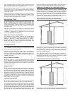
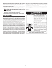
TERMINATION CLEARANCES SIDEWALL POWER VENT
V X
VENT TERMINAL AIR SUPPLY INLETAREA WHERE TERMINAL IS NOT PERMITTED
v
v
A
G
V
FIXED
CLOSED
FIXED
CLOSED
OPERABLE
OPERABLE
V
C
B
B
B
B
F
B
V
V
A
J
V
H
M
X
X
V
V
K
B
E
D
L
POWER VENT
(using room air for combustion)
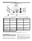
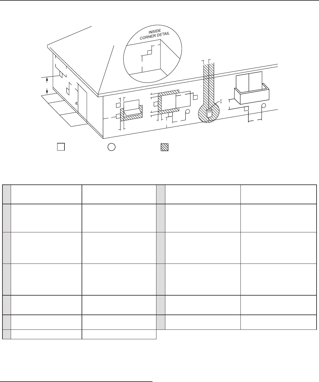
EXTERIOR CLEARANCES FOR SIDEWALL VENT TERMINATION
FIGURE 15.
Vent terminal clearances for “Power Vent” installations. Power Vent congurations use room air for combustion.
US INSTALLATIONS US INSTALLATIONS
A
Clearance above grade, veranda, porch,
deck or balcony
12inches(30cm)
H
Clearance to each side of center line
extended above meter/regulator assembly
3feet(91cm)withinaheight15feet(4.5m)
above the meter/regulator assembly*
B
Clearance to window or door that may
be opened
4feet(1.2m)belowortosideofopening;1
foot(30cm)aboveopening
I
Clearance to service regulator vent outlet
3feet(91cm)*
C
Clearance to permanently closed window 12inches(30cm)*
J
Clearance to a non mechanical air supply
inlet into building or combustion air inlet to
any other appliance
4feet(1.2m)belowortosideofopening;
1 foot
(30cm)aboveopening.
D
Verticalclearancetoventilatedsoft
located above the terminal within a
horizontaldistanceof2feet(61cm)from
the center line of the terminal
12inches(30cm)*
K
Clearance to a mechanical air supply inlet
3feet(91cm)aboveifwithin
10feet(3m)horizontally
E
Clearancetounventilatedsoft 12inches(30cm)*
L
Clearance above paved sidewalk or paved
driveway located on public property
7feet(2.13m)
†
F
Clearance to outside corner 2feet(60cm)*
M
Clearance under veranda, porch, deck, or
balcony
12inches(30cm)‡
G
Clearance to inside corner 18inches(45cm)*
In accordance with the current ANSI Z223.1/NFPA 54, National Fuel Gas Code.
† A vent shall not terminate directly above a sidewalk or paved driveway that is located between two single family dwellings and serves both dwellings.
‡Permittedonlyifveranda,porch,deck,orbalconyisfullyopenonaminimumoftwosidesbeneaththeoor.
*Clearanceinaccordancewithlocalinstallationcodesandtherequirementsofthegassupplierandthemanufacturer’sinstallationinstructions.
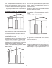
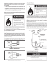
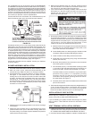
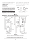
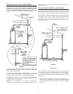
VENT PIPE TERMINATION
The first step is to determine where the vent pipe will terminate.
See Figures 15, 20 and 21. The vent may terminate through a
sidewall as shown in Figure 20 or through the roof as shown
in Figure 21.
The vent system must terminate so that proper clearances are
maintained as cited in local codes or the current edition of the
NationalFuelGasCode,(ANSIZ223.1,12.9.1through12.9.4).
Instructions on proper installation through a sidewall are provided
in Figure 15.
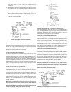
Plan the vent system layout so that proper clearances are
maintained from plumbing and wiring.
Ventpipesservingpowerventedappliancesareclassiedby
buildingcodesas“ventconnectors”.Requiredclearancesfrom
combustible materials must be provided in accordance with
information in this manual under LOCATING THE NEW WATER
HEATER and INSTALLING THE WATER HEATER, and with the
National Fuel Gas Code and local codes.